Configuring with a Web browser
Chapter 2 explains how to access the industrial managed switch for the first time. There are three ways to configure this Ethernet Switch:
Web browser
Telnet console
Serial console
The web browser and the telnet console methods allow users to access the switch over the Internet or the Ethernet LAN, while the serial console method requires a serial cable connection between the console and the switch. There are only a few differences among these three methods. Users are recommended to use the web browser method to configure the system because of its user-friendly interface.
Web-based Management Basics
Users can access the managed switch easily using their web browsers (Internet Explorer 8 or 11, Firefox 44, Chrome 48, or later versions are recommended). We will proceed to use a web browser to introduce the managed switch’s functions.
Default Factory Settings
Below is a list of default factory settings. This information will be used during the login process. Make sure that the computer accessing the switch has an IP address in the same subnet and the subnet mask is the same. Please pay attention that username and password are case sensitive.
IP Address: 192.168.2.1/24
Subnet Mask: 255.255.0.0
Default Gateway: 0.0.0.0
Username: admin
Password: RSAGS@Welotec
Login Process and Main Window Interface
Before users can access the configuration, they must log in. This can simply be done in the following steps.
Launch a web browser
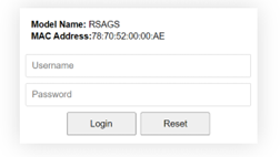
Type in the siwtch IP address (e.g.: http://192.168.2.1, as shown in Figure 2.1.) Note: When the username and the password are left empty, the login prompt will not show.

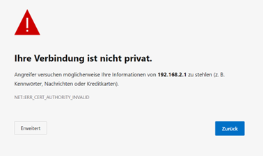
If it is the first time that the users access the managed switch, the web browser such as Google Chrome may detect that the switch does not have a valid certificate authority. The users can proceed by clicking on the Advanced button as shown in Figure 2.2.
Once the Advanced button is clicked, an explanation text will appear below the button as shown in Figure 2.3. Here at the bottom of the web page, there is a hyperlink that the users can click to access the web GUI of the managed switch.
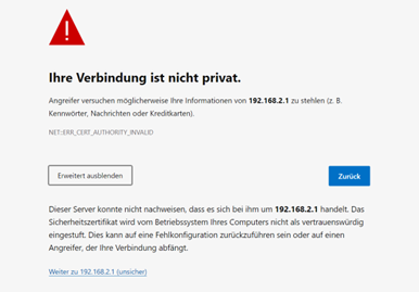
After proceeding through the invalid certificate warning and clicking on the Proceed to 192.168.2.1/24 (unsafe) hyperlink, a login page will be presented shown in Figure 2.4. The user must enter a Username and a Password to access the managed switch. Then press Login.
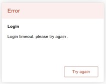
For security purpose, if the user did not enter the username and the password within 30 seconds, the login page will time-out and an error notification page will show up. Even though the user entered the correct username and password, the login procedure will not succeed if the login was done more than 30 seconds after the login page was first accessed. The notification page is shown in Figure 2.5. The user can click on the Try again button to access the login page again.
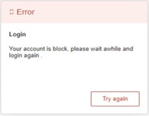
If the user entered wrong passwords more than three times within 3 minutes, the account will be temporary blocked for 15 minutes. An error pop-up notification will be shown as in Figure 2.6. The user can click the Try again button to access the login page after the duration of 15 minutes.
Note:
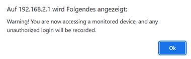
Any unauthorized login to the managed switch will be recorded to device’s syslog. A pop-up notification is shown in Figure 2.7.
After the user logins to the main interface if the user is idle or inactive for more than 5 minutes, the user will be logged out automatically.
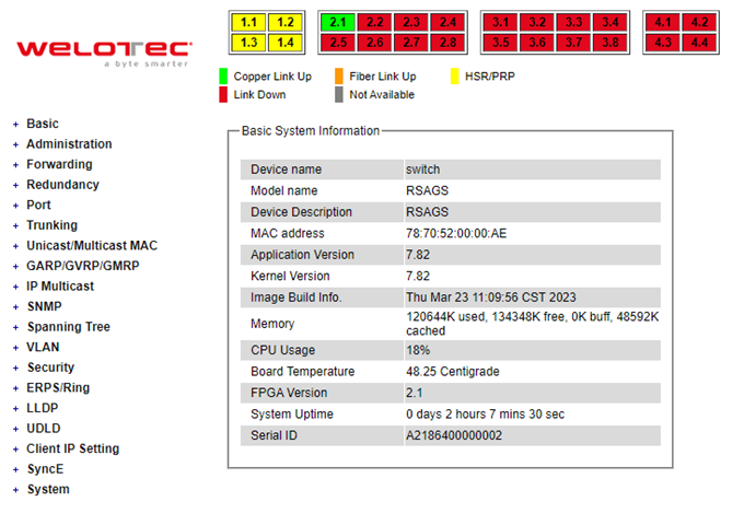
After the login process, the main interface will show up, as shown in Figure 2.8. The main menu (left side of the screen) provides the links at the top-level links of the menu hierarchy and by clicking each item allows lower-level links to be displayed. Note that in this case the Port 2.1 is highlighted in green, indicating that the port is being connected. Detailed explanations of each subsection will be addressed later as necessary.
Basic Information
To help users become familiar with the device, the Basic section provides important details of the switch. This is also the main welcome screen once the user has logged in. The details make it easier to identify different switches connected to the network. The Basic section is categorized into six subsections as shown in the left panel of Figure 2.9.

Sys Info
This subsection provides basic system information of Welotec’s industrial managed switch. The user can check the device name, model name, device description, MAC address, firmware version, image build information, memory usage of the switch, and current board’s temperature. Note that Welotec’s firmware generally consists of application version and kernel version. Figure 2.10 depicts an example of Basic System Information of RSAGS. Table 2.1 summarizes the description of each basic information.
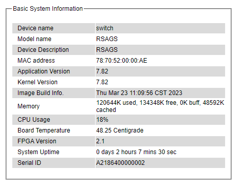
Table 2.1 Descriptions of the Bassic Information:
Label |
Description |
|---|---|
Device name |
The device’s given name which can be set by the user. |
Model name |
The device’s complete model name |
Device Description |
The model type of the device |
MAC address |
The MAC address of the device |
Application Version |
The current application version of the device. |
Kernel Version |
The current kernel version of the device. |
Image Build Info. |
Information about the firmware image such as date of creation |
Memory |
The current RAM’s availability and the size of cached and shared memory. |
CPU Usage |
The current CPU usage information. |
Board Temperature |
The current temperature of the board inside the chassis in degree Celsius a.k.a. Centigrade. |
FPGA Version |
The FPGA version of the device. |
System Uptime |
The current bootup time of the device. |
Device Information Setting
Users can assign device’s details to Welotec’s switch in this subsection. By entering unique and relevant system information such as device name, device description, location, and contact, this information can help identify one specific switch among allother devices in the network that supports SNMP. Please click on the “Update” button to update the information on the switch. Figure 2.11 shows Device Information Setting page of an RSAGS managed switch model. Table 2.2 summarizes the device information setting descriptions and corresponding default factory settings.
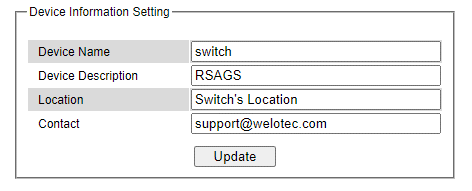
Table 2.2 Descriptions of the System Setting:
Label |
Description |
Factory Default |
|---|---|---|
Device Name |
Specifies a particular role or application of different switches. The name entered here will also be shown in Welotec’s Device Management Utility with the max. length of 63 characters. |
switch |
Device Description |
Detailed description of the unit with the max. length of 63 Characters. |
Managed Switch |
Location |
Location of the switch with the max. of length of 63 Characters. |
Switch’s Location |
Contact |
Provides contact information for maintenance. Enter the name of whom to contact in case a problem occurs with the max. length of 63 Characters. |
support@Welotec.com |
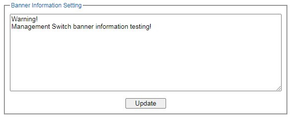
Banner Information Setting
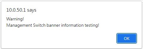
A banner is a message presented to a user who is using the switch. Based on the type of banner you configured for use, the message will be shown to users of switch. Users can assign device’s banner information to Welotec’s switch in this subsection. You can configure the switch to display login banner when user manage switch through the following methods:
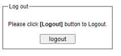
Web GUI Logout
Console
SSH Login
Telent Login
Please click on the “Update” button to update the information on the switch. Figure 2.11 shows Banner Information Setting page of managed switch model.
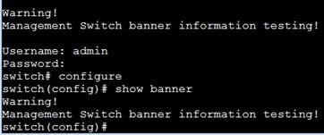
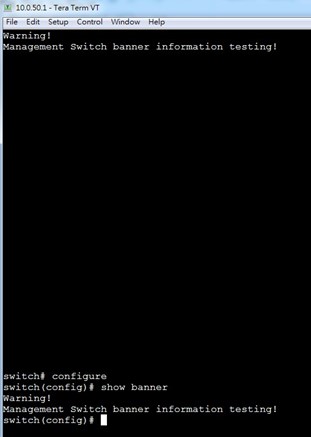
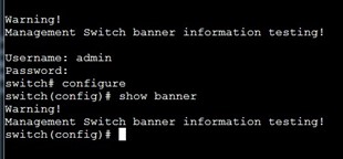
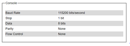
Console
In this chapter, we use a web browser for configuring the switch. For the serial console method, please go to Chapter 3 Configuring with Serial Console for more detail on how to connect console to the switch. The Console here only shows the setting parameters of a serial console’s connection, which can be used by a console software such as Tera Term. Figure 2.17 below shows an example of the serial console’s connection parameters.
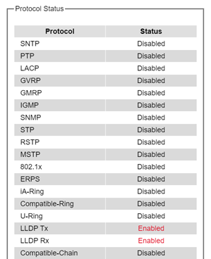
Protocols Status
Protocols Status subsection reports status of all protocols in the switch. While users can view status of all protocols at once in this webpage, the detailed explanation of each protocol and method will be provided in the following sections. Figure 2.18 shows the web interface for the Protocol Status page.
Power Status
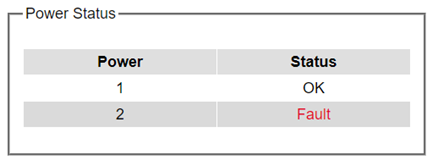
Welotec’s managed switch features dual VDC power supply inputs. For Non-PoE models, 9 – 57 VDC can be supplied to Power Input 1 (V1+ and V1- pins) and/or Power Input 2 (V2+and V2- pins). For PoE models, 45 – 57VDC should be supplied under 802.3af mode and 51 – 57 VDC should be supplied under 802.3at mode. For instance, the RSAGS has the following three power ratings: 9 – 57 VDC with a maximum current of 2.8 Amperes (No PoE mode), 45 – 57 VDC with a maximum current of 1.7 Amperes (802.3af mode), and 51 – 57 VDC with a maximum current of 2.3 Amperes (802.3at mode). Figure 2.19 shows the status of each power input. A “Fault” status means that the power on that supply input is either not connected or the power is not supplied properly.
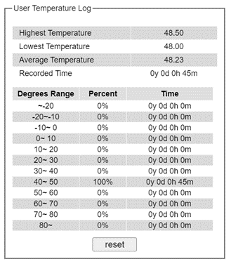
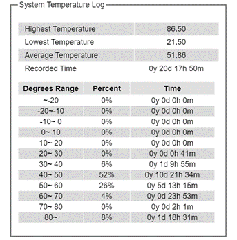
Temperature Log
This subsection provides user and system temperature logs. There are summary statistics and distribution of temperature information for each log. The highest temperature, the lowest temperature and the average temperature are reported in degree Celsius. Additionally, there is a recorded time which shows the time since the temperature log were recorded. Under the summary statistics, there is a table showing the ranges of temperature, percentages of time in each range, and amount of time in each range. The user can reset the user statistics by clicking on the Reset button at the bottom of User Temperature Log. However, the system temperature log cannot be reset by the users. Note that the information is not automatically update. Information provided in this webpage will help the users to monitor the status of the industrial managed switch in harsh environment. The users must click reload on the web browser to update for the latest statistics. Figure 2.20 shows the User Temperature Log box and Figure 2.21 shows the System Temperature Log box.
Note that there is a sensor component in the industrial managed switch which can detect the inside temperature. The software inside the switch can read the sensor’s data and transform it into temperature in a unit of degree Celsius. Because the device is airtight, the inside temperature will be higher than the outside temperature around 20 degrees. For the industry level switches, the lowest operating temperature (outside) will be around -20 to -40 degrees Celsius, and the highest operating temperature (outside) will be around 70 to 85 degrees Celsius.
Administration
In this section, users will be able to configure Account, Auth Server Setting, IP Settings, IPv6 Setting, Ping, Ping6, Mirror Port, System Time, Modbus Setting, PTP, SSH, Telnet, and HTTPS. Figure 2.22 shows the Administration section with the list of its subsections on the left of the screen.
Account
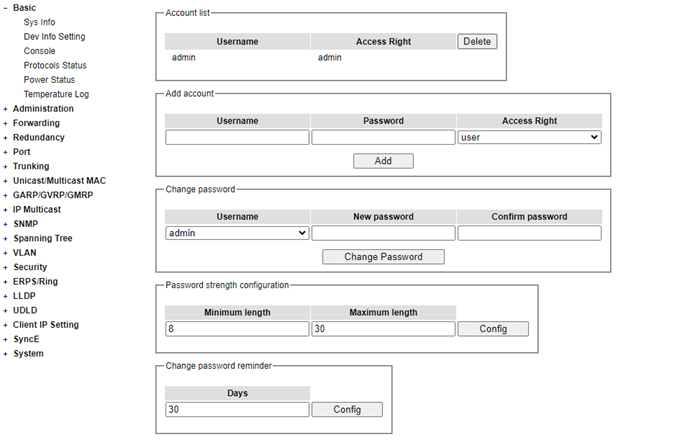
The users with administration access right can create and delete accounts through Administration->Account Section. As shown in Figure 2.23, there are total of four section boxes inside Administration->Account page as the followings: Account list, Add account, Change password, and Password strength configuration. In Account List box (1st row of Figure 2.23), the users and their access rights are listed. There are five types of access right: admin、 user、maintenance1、maintenance2 and maintenance3. Table 2.3 describe permission level of each user. If the user with administration access right would like to delete any account, the user can select the account that would like to be deleted and click “Delete” button. Note that the user without administration access right cannot delete his/her own account. The user whose account was deleted will be logged out immediately.
Table 2.3 Description of each user permission level:
Level |
Name |
Definition |
|---|---|---|
1 |
User |
1. User can read the configure. 2. User cannot set any configure. |
2 |
Maintenance-1 |
1. User can read the configure. 2. User can use Reboot command. |
3 |
Maintenance-2 |
1. User can read the configure. 2. User can use Reboot command. |
4 |
Maintenance-3 |
1. User can read the configure. 2. User can set all the configures but cannot set security command. |
5 |
Admin |
1. User can read the configure. 2. User can set all the configures. |
Note: Security commands
Account Setting
Telnet Setting
SSH Setting
SNMP Setting
x509 certificate
Auth Server Setting
802.1X Setting
In the Add account box (2nd row of Figure 2.23), the user can input a username in the Username textbox as well as input a password in the Password textbox. Then the user can select an appropriate Access Right from the dropdown list for the user before clicking Add button. After clicking it, a new account will be created in the Account List box. A username “admin” with an “admin” Access Right is created as the default. The maximum number of accounts is 15 accounts.
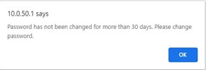
If the user wishes to change password for any account, the user can do so in the Change password box (3rd row of Figure 2.23). Here, the user has to select a username from the Username dropdown box first. Then, input a password that user would like to change it to in new password textbox before re-entering the same password in the Confirm password textbox. The Minimum length and the Maximum length of each password can be configured through the Password strength configuration box in the 4th row of Figure 2.23. The latest row of Figure 2.23 can change password reminder timer, the default days setting is 30 days. Note that the users will be reminded when default setting during the login procedure with a notification to change their passwords if the passwords have not been changed over the last 30 days. Figure 2.24 shows the pop-up notification for changing the password.
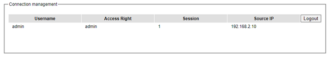
Connection
The Connection sub-menu under the Account menu lists the users who currently access the device under the Connection Management box. Inside the box, the table lists the information of the users with four columns: Username, Access Right, Session, and Source IP is shown in Figure 2.25. Note that logged user will be kicked out automatically when there is no activity for more than 5 minutes.
Auth Server Setting
In addition to the local authentication, the switch can be configured to request for authentication through a centralized RADIUS or TACACS+ server when the local authentication fails. Figure 2.26 shows the setting parameters for authentication server while Table 2.4 summarizes the authentication server settings. For the RADIUS and TACACS+ comparison, please refer to Table 2.5 so that you can choose the solution that best suits your needs.
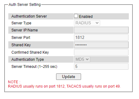
Table 2.4 Authentication Server Settings:
Label |
Description |
Factory Default |
|---|---|---|
Authentication Server |
Enable/disable authentication through a remote authentication server |
Disabled |
Server Type |
ChooseAuthentication Server type: RADIUS or TACACS+. See notes below for a detailed explanation. |
RADIUS |
Server IP/Name |
IP address of the authentication server |
NULL |
Server Port |
Communication port of the authentication server |
1812 |
Shared Key |
The key used to authenticate with the server. Max. 15 characters. |
12345678 |
Confirmed Shared Key |
Re-type the shared key. Max. 15 characters. |
NULL |
Label |
Description |
Factory Default |
Authentication Type |
Authentication mechanism. For RADIUS: MD5. For TACACS+: ASCII, PAP, CHAP, MSCHAP. |
RADIUS is MD5 TACACS+ is ASCII |
Server Timeout (1~255 sec) |
The time out period of waiting for a response from the authentication server. This will affect the time that the next login prompt shows up in case that the server is not available. |
5 |
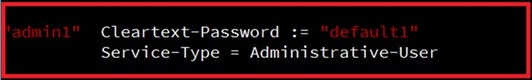
When configuring RADIUS as the authentication server, the system administrator of thr RADIUS server must also make sure that the RADIUS’s service-type attribute of each new user matches that particular user. For example, if a user has an administrative right that user should have read/write priviledge, this user should be set Service-Type attribute on RADIUS server as “Administrative-User”. On the other hand, if a user has only normal privilege that is only read permission, this user should be set Service-Type attribute on RADIUS server as “NAS-Prompt-User”. Note that NAS is referred to Network Access Server or the RSAGS Managed Switch in this case. NAS is a client of RADIUS server. Depicts an example of a user called “admin1” with Cleartext-Password attribute of “default1” and Service-Type attribute of “Administrative-User”.
*NOTE:
RADIUS (Remote Authentication Dial in User Service):
RADIUS is an access server that uses authentication, authorization, and accounting (AAA) protocol for authentication and authorization. It is a distributed security system that secures remote access to networks and network services against unauthorized access. The RADIUS specification is described in RFC 2865, which obsoletes RFC 2138.
Note:
RADIUS support two level account
Service-Type: value “6” Administrative as Admin level
Service-Type: value “7” NAS Prompt as User level
TACACS+ (Terminal Access Controller Access-Control System Plus):
TACACS+ is a security application that provides centralized validation of users attempting to gain access to a router or network access server. The TACACS+ specification is described in Cisco’s TACACS+ RFC draft.
Table 2.5 Comparison of Authentication Server Settings between RADIUS and TACACS+:
RADIUS |
TACACS+ |
|
|---|---|---|
Transport Protocol |
UDP |
TCP |
Authentication and Authorization |
Separates AAA |
Combines authentication and authorization |
Multiprotocol Support |
No |
Yes, support AppleTalk Remote Access (ARA) and NetBIOS protocol |
Confidentiality |
Only passwordis encrypted |
Entire packet is encrypted |
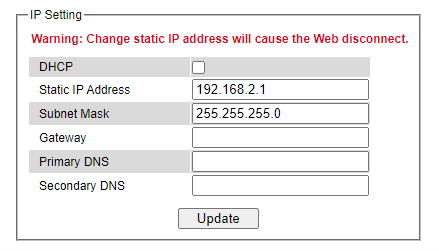
IP Setting
This subsection is divided into two parts: IP Setting and Current IP address information. In this subsection, the user may modify network settings of Internet Protocol version 4 (IPv4) for the managed switch, e.g.: Static IP Address, Subnet Mask, Gateway, Primary DNS (domain name server), and Secondary DNS. As shown in Figure 2.28, the user can choose to enable DHCP (Dynamic Host Configuration Protocol) by checking the box behind it. That is the IP address and related information can be automatically obtained from a DHCP server in the local network thus reducing the work for an administrator. By disabling this function (DHCP’s box is unchecked), the user has an option to setup the static IP address and related fields manually. Please click on the Update button to update the IP configuration on the switch. A system reboot is required after each update, so the new network settings can take effect. The user will need to manually update the new IP address in the URL field of the web browser if the IP address of the managed switch is changed.
The second part of IP Setting section is the Current IP address information part as shown in Figure 2.29. In this part, the current IP address information of the managed switch is listed. The description of each field and its default value are summarized in Table 2.6.
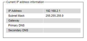
Table 2.6 Descriptions of IP Settings:
Label |
Description |
Factory Default |
|---|---|---|
DHCP |
By checking this box, an IP address and related fields will be automatically assigned. Otherwise, users can set up the static IP address and related fields manually. |
Uncheck |
Static IP Address |
Display current IP address. Users can also set a new static IP address for the device. |
192.168.2.1/24 |
Subnet Mask |
Display current Subnet Mask or set a new subnet mask. |
255.255.0.0 |
Gateway |
Show current Gateway or set a new one. |
10.0.0.254 |
Primary DNS |
Set the primary DNS IP address to beused by your network. |
168.95.1.1 |
Secondary DNS |
Set the secondary DNS IP address. The Ethernet switch will locate the secondary DNS server if it fails to connect to the Primary DNS Server. |
NULL |
IPv6 Setting
This subsection enables Welotec’s industrial managed switch to operate in Internet Protocol version 6 (IPv6) network. The webpage is subdivided into two parts: IPv6 Setting and Current IPv6 address information. The first part called IPv6 Setting is shown in Figure 2.30 and allows the users to configure the Domain Name Service (DNS) for IPv6 network. The users have a choice to enable or disable the Manual DNS by checking the box behind it. When the Manual DNS option is checked, the users will be able to enter the IPv6 addresses of the Primary DNS and the Secondary DNS. If the users change any DNS setting, please clicking on the Update button to allow the new configuration to take effect. Table 2.7 explains each field in the IPv6 Setting webpage.
The second part called Current IPv6 address information is shown in Figure 2.31. This part of the web page summarizes the current IPv6 address information of the managed switch, which are the Global Unicast Address, Link-Local Address, Gateway, Primary DNS, and Secondary DNS.
Table 2.7 Description of IPv6 Setting:
Label |
Description |
Factory Default |
|---|---|---|
Autoconfig |
By checking this box, all IPv6 setting will be automatically configured for the users. This option is based on the stateless autoconfiguration in which the switch uses information in router advertisement messages to configure an IPv6 address. The address will be a concatenation of first. 64 bits from the router advertisement source address with the Extended Unique Identifier (EUI-64). |
Uncheck |
DHCPv6 |
By checking this box, an IPv6 address and related fields will be automatically assigned from a DHCPv6 server in the network. This is a stateful auto configuration in which the switch will generate a DHCP solicit message to the ALLDHCP-agents multicast address to find DHCPv6 server. Otherwise, users can set up the IPv6 address manually. |
Uncheck |
Manual |
By checking this box, users must provide Global Unicast Address, Prefix Length, and Gateway address in the following fields. Note that when this option is checked, the next three fields will become active for setting. |
Uncheck |
Global Unicast Address |
Set an IPv6 address that is routable across the Internet and its three high-level bits are 001. The IPv6 address is in the format 2XXX::/3. |
NULL |
Link Local Address |
An IPv6 unicast address that can be automatically configured on any interface using the link-local prefix FE80::/10 (1111 1110 10) and the interface identifier in the modified EUI-64 format. Not necessarily bound to the MAC address. |
fe80::260:e9ff:fe26:ba1f/64 |
Prefix Length |
Set a prefix length for the IPv6 address in previous field. |
NULL |
Gateway |
Set the IPv6 address of an IPv6 Gateway |
NULL |
Manual DNS |
By checking this box, user must manually provide Primary and Secondary DNS addresses for IPv6. Note that when this option is checked, the next two fields will become active for setting. |
Uncheck |
Primary DNS |
Set the primary DNS IPv6 address to be used by your network. |
NULL |
Secondary DNS |
Set the secondary DNS IPv6 address. The Ethernet switch will locate the secondary DNS server if it fails to connect to the Primary DNS Server. |
NULL |
Ping
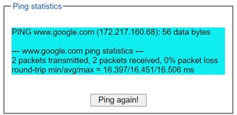
Welotecs managed switch provides a network tool called Ping for testing network connectivity in this subsection. Ping is a network diagnostic utility for testing reachability between a destination device and the managed switch. Note that this utility is only for IPv4 address. The Ping utility for IPv6 will be provided in the next subsection. Figure 2.32 shows the user interface for using the Ping command.
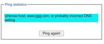
Users can enter an IP address or a domain name into the field to verify network connectivity as shown in Figure 2.33. After entering the IP address/name, please click “Ping” button to run the ping function. Example of successful ping results shown in Figure 2.34 while a failure ping result is depicted in Figure 2.35.
Note: If users enter a domain name instead of IP address, they should assign a DNS first. This can be done through Administration->IP Setting as shown in Section “IP Setting”.
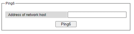
Ping6
Ping6 is a corresponding network diagnostic utility for testing reachability between a destination device and the managed switch in IPv6 network. Figure 2.36 shows the user interface for using the Ping command.
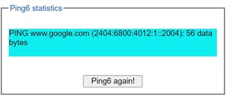
Users can enter an IPv6 address into the field to verify network connectivity. After entering the IPv6 address, please click “Ping6” button to start the ping function. Examples of successful ping6 results are shown in Figure 2.37.
Mirror Port
To help the network administrator keeps track of network activities, the managed switch supports port mirroring, which allows incoming and/or outgoing traffic to be monitored by a single port that is defined as a mirror port. Note that the mirrored network traffic can be analyzed by a network analyzer or a sniffer for network performance or security monitoring purposes. Figure 2.38 shows the Mirror Port webpage. The descriptions of port mirroring options are summarized in Table 2.8.
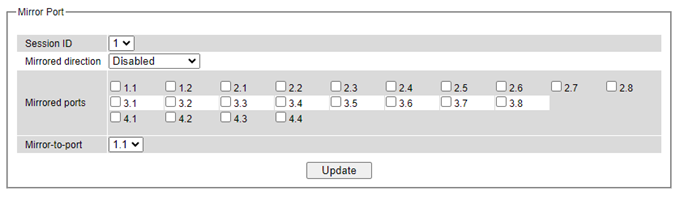
Note: Overflow will occur in the total throughput of the monitoring ports exceeds what the mirror port can support.
Table 2.8 Description of Port Mirroring Options
Label |
Description |
Factory Default |
|---|---|---|
Mirrored direction |
Select the monitoring direction. -Disable: to disable port monitoring. -Ingress: To monitor input data stream of monitored ports only. -Egress: To monitor output data stream of monitored ports only. -Ingress/Egress: To monitor both input and output data stream of monitored ports. |
Disabled |
Mirrored Port |
Select the ports that will be monitored. |
Unchecked all |
Mirror-to-port |
Select the mirror port that will be used to monitor the activity of the monitored ports. |
(Port)1.1 |
System Time
Welotec’s industrial managed switch has internal calendar (date) and clock (or system time) which can be set manually or automatically. Figure 2.39 shows the System Time and SNTP webpage. The users have options to configure Current Date and Current Time manually. There is a drop-down list of Time Zone which can be selected for the local time zone. If the switch is deployed in a region where daylight saving time is practiced (see note below for explanation), please check the Enable option for Daylight Saving Time. Then, the users will have to enter the Start Date, End Date, and Offset in hour(s).
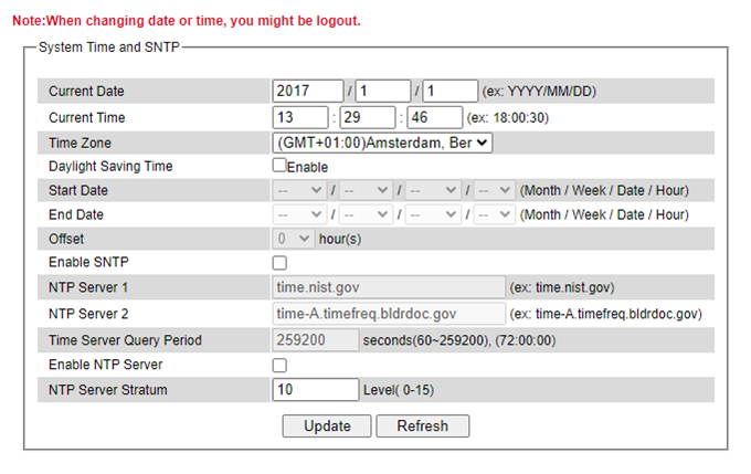
For automatically date and time setting, the users can enable Simple Network Time Protocol (SNTP) by checking the Enable SNTP option (see note below for explanation). Then, the users must enter the NTP Server 1 and NTP Server 2 which will be used as the reference servers to synchronize date and time to. The users can specify the Time Server Query Period for synchronization which is in the order of seconds. The value for this period will depend on how much clock accuracy the users want the switch to be. Finally, the managed switch can become a network time protocol server for the local devices by checking the box behind the Enable NTP Server option. Description of each option is provided in Table 2.9.
Table 2.9 Descriptions of the System Time and the SNTP:
Label |
Description |
Factory Default |
|---|---|---|
Current Date |
Allows local date configuration in yyyy/mm/dd format |
None |
Current Time |
Allows local time configuration in local 24-hour format |
None |
Time Zone |
The user’s current local time |
(GMT+08:00) Taipei |
Daylight Saving Time |
Enable or disable Daylight Saving Time function |
Unchecked |
Start Date |
Define the start date of daylight saving |
NULL |
End Date |
Define the end date of daylight saving |
NULL |
Offset |
Decide how many hours to be shifted forward/backward when daylight saving time begins and ends. See note below. |
0 |
Enable SNTP |
Enables SNTP function. See note below. |
Unchecked |
NTP Server 1 |
Sets the first IP or Domain address of NTP Server. |
time.nist.gov |
NTP Server 2 |
Sets the second IP or Domain address of NTP Server. Switch will locate the 2nd NTP Server if the 1st NTP Server fails to connect. |
time-A.timefreq.bldrdoc.gov |
Time Server Query Period |
This parameter determines how frequently the time is updated from the NTP server. If the end devices require less accuracy, longer query time is more suitable since it will cause less load to the switch. The setting value can be in between 60 – 259200 (72 hours) seconds. |
259,200 seconds. |
Enable NTP Server |
This option will enable network time protocol (NTP) daemon inside the managed switch which allows other devices in the network to synchronize their clock with this managed switch using NTP. |
Unchecked |
Note: Daylight Saving Time: In certain regions (e.g. US), local time is adjusted during the summer season in order to provide an extra hour of daylight in the afternoon, and one hour is usually shifted forward or backward. SNTP: Simple Network Time Protocol is used to synchronize the computer systems’ clocks with a standard NTP server: Examples of two NTP servers are time.nist.gov and time-A.timefreq.bldrdoc.gov.
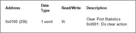
Modbus Setting
Welotec’s managed switch can be connected to a Modbus network using Modbus TCP/IP protocol which is an industrial network protocol for controlling automation equipment. The managed switch’s status and settings can be read and written through Modbus TCP/IP protocol which operates like a Management Information Base (MIB) browser. The managed switch will be a Modbus slave which can be remotely configured by a Modbus master. The Modbus slave address must be set to match the setting inside the Modbus master. To access the managed switch, a Modbus Address must be assigned as described in this subsection. A Modbus memory mapping table, which lists all the register’s addresses inside the managed switch and their descriptions, is provide in Chapter 6 Modbus Memory Map. Figure 2.40 shows the Modbus Setting webpage.
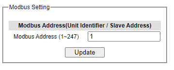
Figure 2.40 shows the webpage that users can set up the Modbus ID address. Users can use Modbus TCP/IP compatible applications such as Modbus Poll to configure the switch. Note that Modbus Poll can be download from http://www.modbustools.com/download.html. The Modbus Poll 64-bit version 7.0.0, Build 1027 was used in this document. Welotec does not provide this software to the users. Tutorial of Modbus read and write examples are illustrated below.
Note: The switch only supports Modbus function code 03, 04 (for Read) and 06 (for Write).
Read Registers (This example shows how to read the switch’s IP address.)
Make sure that a supervising computer (Modbus Master) is connected to your target switch (Modbus Slave) over Ethernet network.
Launch Modbus Poll in the supervising computer. Note a registration key may be required for a long term use of Modbus Poll after 30-day evaluation period. Additionally, there is a 10-minute trial limitation for the connection to the managed switch.
Click Connect button on the top toolbar to enter Connection Setup dialog by selecting Connect… menu as shown in Figure 2.42.
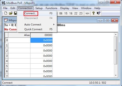
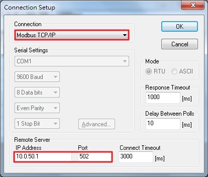
Select Modbus TCP/IP as the Connection mode and enter the switch’s IP address inside the Remote Modbus Server’s IP Address or Node Name field at the bottom as shown in Figure 2.43. The Port number should be set to 502. Then click OK button.
On the window Mbpoll1, select multiple cells from row 0 to row 2 by clicking on cells in second column of row 0 and row 2 while holding the shift key as shown in Figure 2.44.
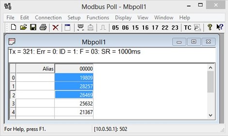
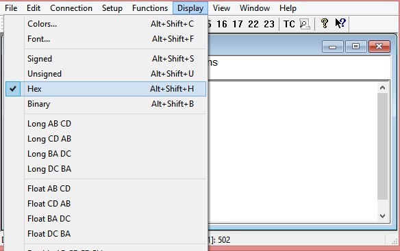
Set Display mode of the selected cells in previous step to HEX (hexadecimal) by selecting Display pulldown menu and choosing the Hex as shown in Figure 2.45.
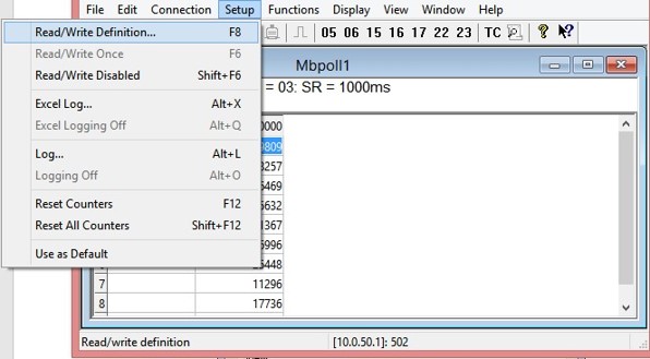
Click on the Setup pull-down menu and choose Read/Write Definition… as shown in Figure 2.46.
Enter the Slave ID in the Modbus Poll function as shown in Figure 2.47, which should match the Modbus Address = 1 entered in Figure 2.40 in Section 2.3.9 (Modbus Setting).
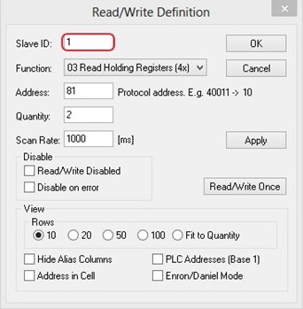
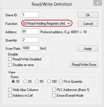
Select Function 03 or 04 because the managed switch supports function code 03 and 04 as shown in Figure 2.48.
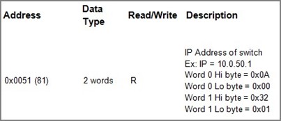
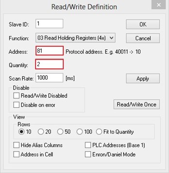
Set starting Address to 81 and Quantity to 2 as shown in Figure 2.49.
Click OK button to read the IP address of the switch.
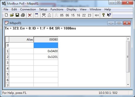
Modbus Poll will get the values 0x0A, 0x00, 0x32, 0x01, which means that the switch’s IP is 10.0.50.1as shown in Figure 2.50.
Write Registers (This example shows how to clear the switch’s Port Count (Statistics).).
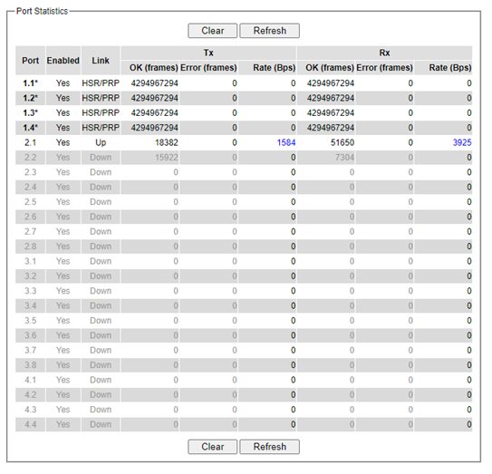
Check the switch’s Port TX/RX counts in Port Statistics page (described in Section 2.6.4) as shown in Figure 2.52.
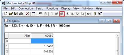
Click function 06 on the toolbar as shown in Figure 2.53.
Set Address to 256 and Value (HEX) to 1, then click “Send” button.
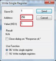
Check Port Statistics (described in Section2.6.4) in the managed switch’s Web UI. The packet count is now cleared.
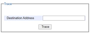
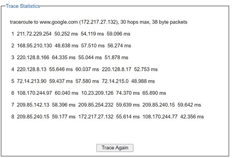
TraceRt
Welotec’s managed switch also provides another network diagnostic tool called TraceRT or traceroute for checking possible network’s routes or paths and determining transit delay of packets across an IP network. TraceRT webpage is shown in Figure 2.56. The users can enter the URL or IP address of a destination in the Destination Address field. After clicking on the Trace button, the switch will report a list of Trace Statistics as shown in Figure 2.57 as an example. Each entry in the report will provide an address of each successive host along the route or path until it reaches the destination together with sum of the mean times (in milliseconds) in each hop.
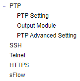
Precision Time Protocol (PTP)
The Precision Time Protocol (PTP) is a high-precision time protocol. It can be used with measurement and control systems in local area network that require precise time synchronization. This menu is divided into two submenus: PTP Setting and Output Module as shown in Figure 2.58.
PTP Setting
The PTP can be set in this PTP Setting webpage. Figure 2.60 shows the PTP Configuration webpage in which the user can configure PTP and check its status. The lower part of Figure 2.60 allows the users to enable or disable the PTP function per port and check their status.
To enable PTP on the managed switch, please check the Enabled box behind the State option as shown in Figure 2.60. Note that the PTP will not be enabled per port if this State option is not checked. Please see description of PTP configuration in Table 2.10 and description of PTP port information in Table 2.11. Note that after setting the desired PTP options, please click Update button to allow the new configuration to take effect.
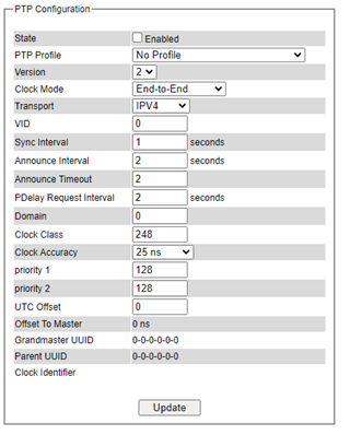
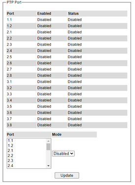
Table 2.10 Description of PTP Setting
Label |
Description |
Factory |
|---|---|---|
State |
Enabled/Disable the PTP function. This is the main option that needs to be enabled so that the port’s PTP function will work according to other parameters defined in this table. |
Unchecked |
PTP Profile |
Select PTP Profile, RSAGS support “No Profile”, “Default Profile”, “61850 Power Profile” and “C37.238 Power Profile” |
No Profile |
Version |
Set the PTP operation version. Note only v2 (IEEE 1588-2008) are supported in RSAGS. |
2 |
Clock Mode |
Select clock type of the PTP (Precision Time Protocol). The switch has four modes: End-End Boundary Clock, End-End Transparent Clock (TC), Peer-Peer Boundary Clock, and Peer-Peer Transparent Clock (TC). |
End-to-End |
Transport |
Select Ethernet (layer 2) multicast transport or layer 3 (UDP/IPv4) multicast transports for PTP (Precision Time Protocol) messages. |
IPV4 |
VID |
Set the VLAN tagged ID in PTP Frames |
0 |
Sync Interval |
Set the interval time of the sync packet in second. The smaller the interval, the frequent the sync packet, which will cause more load to the device and network. |
1 |
Announce Interval |
Set the interval time of the packet announcement. The smaller the interval, the frequent the announce, which will cause more load to the device and network. |
2 |
Announce Timeout |
Set the timeout value for receiving announce messages. |
2 |
PDelay Request Interval |
Set the interval time of the PDelay request packet. The smaller the interval, the frequent the sync packet, which will cause more load to the device and network. Note this is only supported in RSAGS. |
2 |
Domain |
Set the domain number field in 1588 packet |
0 |
Clock Class |
Clock Class represents clock’s accuracy level. It is an attribute of an ordinary or boundary clock. It denotes time traceability or frequency distributed by the grandmaster clock. Please refer to IEEE 1588-2008, Table 5 for definitions, allowed values, and interpretation. |
248 |
Clock Accuracy |
The PTP master issues according to the standard, an announce packet describing its properties. This is relevant for BMCA (Best master clock algorithm) to correctly designate the best clock on the network. |
25 ns |
priority 1 |
Set the clock priority 1 (PTP version 2). The lower values take precedence to be selected as the master clock in the best master clock algorithm (BMCA), 0 = highest priority, 255 = lowest priority. |
128 |
priority 2 |
Set the clock priority 2 (PTP version 2). The lower values take precedence to be selected as the master clock in the best master clock algorithm (BMCA), 0 = highest priority, 255 = lowest priority. |
128 |
UTC Offset |
Coordinated Universal Time (UTC) offset value |
0 |
Offset to Master |
The offset time to the master clock |
None |
Grandmaster Identity |
The Grandmaster identity for PTP version 2 |
None |
Parent UUID |
The parent master identity for PTP version 2 |
None |
Clock Identifier |
The clock identity for PTP version 2 |
Empty |
Note: The Best Master Clock Algorithm (BMCA) is a key to the resiliency of the Precision Time Protocol (PTP). In the time synchronized network, there usually is a Grandmaster clock who synchronizes its clock with the accurate UTC clock from Global Positioning System (GPS). If a Grandmaster clock loses its GPS synchronization or gets disconnected due to a network fault or for other unknown reasons, the BMCA will allows another clock to automatically take over the duties of the Grandmaster clock and continue as a new Grandmaster.
Table 2.11 Description of PTP Port Setting:
Label |
Description |
Factory Default |
|---|---|---|
Port |
Port number |
- |
Enabled |
This is the port’s mode information which indicates whether the port’s PTP function is enabled or disabled. |
Disabled |
Status |
This is PTP’s per port operation status. If the per port function is enabled, but the status is still disabled, please enable the PTP master option. |
Disabled |
Mode |
Enabled/Disabled PTP per port function |
Disabled |
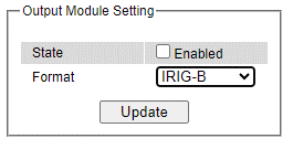
Output Module
RSAGS can be equipped with optional output modules. These output modules support multiple legacy standards, such as IRIG-B, BCD, BJT, ST with checksum, ST which can be enabled and selecting the desired format as shown in Figure 2.61.
Secure Shell - SSH
The managed switch can be managed using command line interface (CLI) as described in Chapter 4. The users have option to remotely connect to the managed switch using either secure shell (SSH) or Telnet through any of its port. In this subsection, SSH will be introduced and then Telnet will be discussed in the next subsection. SSH was designed to replace Telnet and other insecure remote shell protocols that sends data or command in plaintext. SSH uses encryption to secure its data or command over an unsecure network.
To enable the SSH, please check the Enabled box behind the SSH option in Figure 2.62. At the beginning, the Server will send a public key to a client, and the Client will check if the received public key is correct. If it is not correct, the Server will refuse the connection. Please click “Generate” button to change and regenerate the Server.
Key then obtain another public key from Server as shown in Figure 2.62. And the managed switch also supports user upload x.509 certificate as asymmetric key.
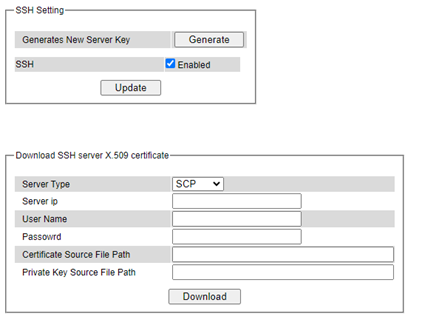
Table 2.12 Descriptions of SSH copy certificate:
Label |
Description |
|---|---|
Server Type |
Choose server type to copy file, support options: SFTP/ SCP |
Server IP |
Server IP address |
Password |
User password for the file server |
User Name |
Username for the file server |
Certificate Source File Path |
The path of certificate file stored on the file server |
Private Key Source File Path |
The path of the private key file stored on the file server. |
Download |
To download file from the file server to device |
Note:
The managed switch supports SSH version 2 (SSH2)
The server key is re-generated when the managed switch is reset to its factory default setting, or a received key is non-existent.
SSH version 2 has the following features:
Client programs that use SSH can perform remote logins, remote command execution, and secure file copying across a network.
Several selectable encryption algorithms and authentication mechanisms are supported by the SSH.
An SSH agent can cache keys for easy access in later session.
Encryption ciphers, e.g.: Triple Data Encryption Standard (3DES) and Advanced Encryption Standard (AES).
The use of sound cryptographic Message Authentication Code (MAC) algorithms for integrity checking. Examples of secure hash (functions) algorithms which are MAC algorithms in SSH version 2 are the Message Digest algorithm5 (MD5) and Secure Hash Algorithm 1 (SHA-1).
Support for public key certificates.
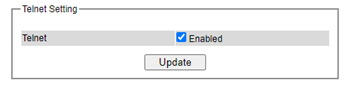
Telnet
This subsection allows the users to set the Telnet option for the managed switch. The command line interface (CLI) configuration using Telnet (as described in Chapter 4) or SSH (previous section) are the same except that the SSH encrypts the communication data. For the Telnet administration, the managed switch only provides the enable or disable function selectable in this webpage. The default setting for Telnet is enabled. Clicking on the Update button when you change the option to update it on the managed switch. Figure 2.63 shows the Telnet setting webpage. Note that the users are recommended to use SSH instead of Telnet for higher security protection of your managed switch.
HTTPS
This subsection enables the users to set the HTTPS (Hypertext Transfer Protocol Secure) for the web-based management user interface of the switch as shown in Figure 2.64. This option will encrypt the normal HTTP message between the switch and the client PC to secure their communication over the network. To access the web GUI when this option is enabled, the users must access the switch via https://192.168.2.1/24 for enhanced security during device configuration. Note that once this option is enabled, every HTTP request for web console of the managed switch will be forced to redirect to https connection. Clicking on the Update button when you change the option to update it on the managed switch. And HTTPS creates a secure channel over an insecure network via certificate key, user can download x.509 certificate as asymmetric key.
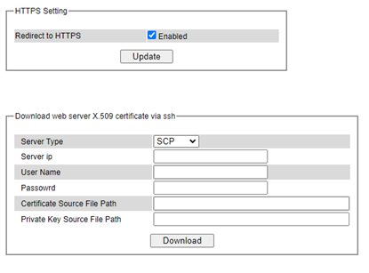
Table 2.13 Descriptions of HTTPS copy certificate:
Label |
Description |
|---|---|
Server Type |
Choose server type to copy file, support options: SFTP/ SCP |
Server IP |
Server IP address |
Password |
User password for the file server |
User Name |
Username for the file server |
Certificate Source File Path |
The path of certificate file stored on the file server |
Private Key Source File Path |
The path of the private key file stored on the file server. |
Download |
To download file from the file server to device |
sFlow
sFlow, short for “sampled flow”, is an industry standard for packet export at Layer 2 of the OSI model for monitoring switched networks through random sampling of packets on switch ports and time-based sampling of port counters. The sampled packets and counters (referred to as flow samples and counter samples, respectively) are sent as sFlow UDP datagrams to a central network traffic monitoring server. This central server is called an sFlow receiver or sFlow collector.
The UDP payload contains the sFlow datagram. Each datagram provides information about the sFlow version, the originating device’s IP address, a sequence number, the number of samples it contains and one or more flow and/or counter samples.
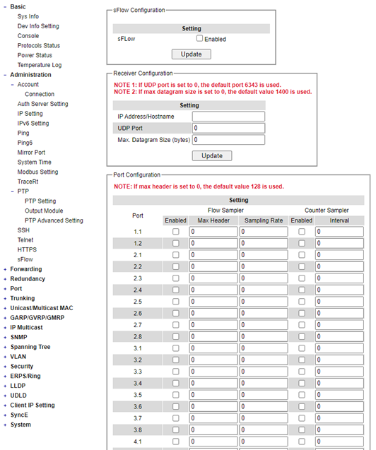
Table 2.14 Descriptions of sFlow Setting:
Label |
Description |
Factory Default |
|
|---|---|---|---|
sFlow Configuration |
|||
Enabled |
Check the box to enable/disable sFlow feature |
Uncheck |
|
Receiver Configuration |
|||
IP Address/Hostname |
The IP address of sFlow receiver |
Null |
|
UDP Port |
The UDP port number of sFlow receiver |
0 |
|
Max. Datagram Size (bytes) |
The maximum number of data bytes that can be sent in a single sample datagram |
0 |
|
Port Configuration |
|||
Flow Sampler |
Enabled |
Check the box to enable/disable the status of flow sampling on specific port(s). |
Uncheck |
Max Header |
The maximum number of bytes that should be copied from a sampled packet to the sFlow datagram |
0 |
|
Sampling Rate |
Set to N to sample on average 1/Nth of the packets transmitted/received on the port |
0 |
|
Counter Sampler |
Enabled |
Check the box to enable/disable the status of counter polling on specific port(s). |
Uncheck |
Interval |
With counter polling enabled, this specifies the interval - in seconds |
0 |
Forwarding
There are many network technologies for forwarding packets over network. In this industrial managed switch, three main technologies are implemented: QoS, rate control, and storm control. Figure 2.67 depicts the submenus under the Forwarding section.
QoS
Quality of Service (QoS) is the ability to provide different priority to different applications, users, or data flows. QoS guarantees a certain level of performance to a data flow by using the following metrics: transmitted bitrate, bit error rate, delay, jitter, and probability of packet dropping. QoS guarantees are important if the network capacity is insufficient, especially for application that requires certain bit rate and is delay sensitive. For any network that is best effort, QoS cannot be guaranteed, except that resource is more than sufficient to serve users. Controlling network traffic needs a set of rules to help classify different types of traffic and define how each of them should be treated as they are being transmitted. This managed switch can inspect both 802.1p Class of Service (CoS) tags and DiffServ tags called Differentiated Services Code Point (DSCP) to provide consistent classification. In the QoS section, three QoS mechanisms are included: queuing methods or packet scheduling disciplines in Setting section, CoS Queuing Mappingsection, and DSCP Mapping section, as shown in Figure 2.68. Table 2.15 summarizes the descriptions of QoS Setting.
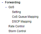
Table 2.15 Descriptions of QoS Setting:
Label |
Description |
Factory Default |
|---|---|---|
Setting |
Queuing Methods (packet scheduling disciplines) includes Strict Priority, Weighted Round-Robin, and Deficit Round Robin. See notes in the following subsection for detailed descriptions and comparison. |
Strict Priority |
Header Mapping |
CoS Queuing Mapping and DSCP Mapping For 802.1p CoS only, switch only checks Layer 2 (L2) 802.1p CoS priority bits. For DiffServ, switch checks DiffServ Code Point (DSCP). See notes below for a detailed description. |
Both 802.1p CoS and DiffServ |
QoS Setting
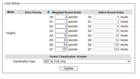
Three types of queuing methods are configurable in this managed switch: Strict Priority, Weighted Round-Robin, and Deficit Round-Robin. In Strict Priority, the QoS scheduler allows the highest priority queue to preempt other queues as long as there are still packets waiting to be transmitted in the highest priority queue. This mode guarantees that traffic in the highest queue is always transmitted first. Only if the high priority queues are empty, the lower priority queues can be transmitted. Queue 0 (Q0) to Queue 7 (Q7) are ranked from the lowest priority queue to the highest priority queue. Therefore, packets in Q7 will be all transmitted first before packets in Q6, and packets in Q6 will all be sent first before packets in Q5, and so on in this order. Weighted Round Robin (WRR) is the simplest approximation of generalized processor sharing (GPS). In WRR, each packet flow or connection has its own packet queue in a network interface controller. It ensures that all service classes have access to at least some configured amount of network bandwidth to avoid bandwidth starvation. However, WRR has a limitation, as it is unfair with variable length packets. It only provides the correct percentage of bandwidth to each service class only if all of the packets in all the queues are the same size or when the mean packet size is known in advance. Usually, a weight of each queue is set proportion to requested bit rate. Each queue is served proportionally to its weight for a service cycle. Deficit WRR (DWRR) addressed the limitation of WRR on unfairness over variable size. Each queue is configured with a weight, a deficit counter (total number of bytes that the queue is permitted to transmit each time visited by the scheduler), and a quantum of service (bytes). DWRR scans all non-empty queues in sequence. When a nonempty queue is selected, its deficit counter is incremented by its quantum value. Then, the value of the deficit counter is the maximal number of bytes that can be sent at this turn. If the deficit counter is greater than the packet’s size at the head of the queue, this packet can be sent, and the value of the counter is decremented by the packet size. Then the size of the next packets is compared to the counter value. Once the queue is empty or the value of the counter is insufficient, the scheduler will skip to the next queue. If the queue is empty, the value of the deficit counter is reset to 0. If the packet size is too small, the scheduler has to visit queues too many times before serving a queue. But if the packet size is too large, some short-term unfairness may arise. It is fair only over a time scale longer than a round time. At the shorter time scale, some flows may get more service. Small packet size or high transmission speed reduce the round time. Figure 2.69 depicts the QoS Setting webpage. By default, the QoS in the managed switch works under the Strict Priority mode. For Weighted Round Robin, packet weights of Q0 to Q7 are set in term of packet as followings.
COS Q0 = 2 packets
COS Q1 = 1 packet
COS Q2 = 4 packets
COS Q3 = 8 packets
COS Q4 =16 packets
COS Q5 = 32 packets
COS Q6 = 64 packet
COS Q7 = 127 packets
Weight of Deficit Round Robin is double the number of packets of WRR, but it is in term of Kbytes instead as shown in the last column of Figure 2.69.
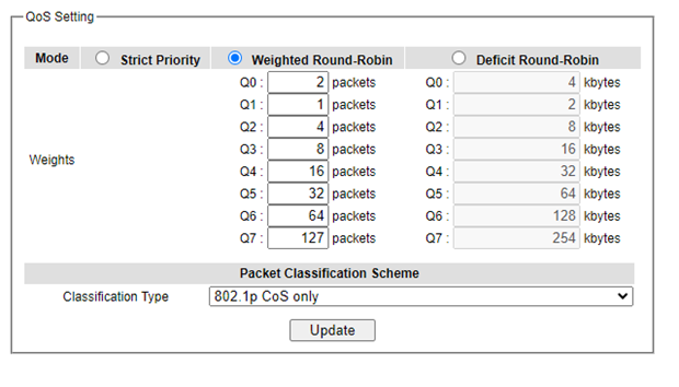
At the bottom of the QoS Setting webpage in Figure 2.69, the users can select the packet classification scheme that will be used by the managed switch. There are two classification types to choose from the drop-down list: 802.1p CoS only or Both 802.1p CoS and DiffServ. The default classification type is 802.1p CoS only. Note that after changing the schedule discipline, setting the desired weights if any for the WRR or DWRR, or selecting the classification type, please click on the Update button to enable them on the switch.
CoS Queue Mapping
802.1p CoS is the QoS technique developed by the IEEE P802.1p working group, known as Class of Service (CoS) mechanism at Media Access Control (MAC) level. It is a 3-bit field called the priority code point (PCP) within an Ethernet frame header (Layer 2) when using VLAN tagged frames as defined by IEEE 802.1Q. It specifies a priority value between 0 and 7 that can be used by QoS to differentiate traffic. When this option is enabled, the switch inspects the 802.1p CoS tag in the MAC frame to determine the priority of each frame. The switch can classify traffic based on a valid 802.1p (CoS - Class of Service) priority tag. These options allow users to map Priority Code Point (PCP) within an Ethernet frame header to different CoS priority queues as shown in Figure 2.70. The user can choose the desired CoS Priority Queue from the drop-down list from Q1 to Q7 for each PCP value. Descriptions of priority queue in CoS Queue Mapping page are summarized in Table 2.16.
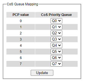
Table 2.16 Priority queue descriptions
Label |
Description |
Factory Default |
|---|---|---|
PCP |
Priority Code Point within the Ethernet frame header. PCP 0 is the lowest priority and 7 is the highest priority. |
PCP 0 ->Q0; PCP 1 ->Q0; PCP 2 ->Q1; PCP 3 ->Q1; PCP 4 ->Q2; PCP 5 ->Q2; PCP 6 ->Q3; PCP 7 ->Q3; |
CoS Priority Queue |
The priority queue that a specific Ethernet frame needs to be assigned into. |
DSCP Mapping
DiffServ/ToS stands for Differentiated Services/Type of Services. It is a networking architecture that specifies a simple but scalable mechanism for classifying network traffic and providing QoS guarantees on networks. DiffServ uses a 6-bit Differentiated Service Code Point (DSCP) in the 8-bit differentiated services field (DS field) in the IP header for packet classification purposes. The DS field and ECN field replace the outdated IPv4 TOS field in IPv4 to make per-hop behavior decisions about packet classification and traffic conditioning functions, such as metering, marking, shaping, and policing.
The RFCs (Request for Comments) do not dictate the way to implement Per-Hop Behaviors (PHBs). Welotec implements queuing techniques that can base their PHB on the IP precedence or DSCP value in the IP header of a packet. Based on DSCP or IP precedence, traffic can be put into a particular service class. Packets within a service class are treated the same way. DiffServ allows compatibility with legacy routers, which only supports IP Precedence, since it uses the DiffServ Code Point (DSCP), which is the combination of IP precedence and Type of Service fields.
TOS (Type of Service) of the switch can be configured with the default queue weights as shown in Figure 2.71. Note that the TOS consists of DSCP (Differentiated Service Code Point (6 bits)) and ECN (Explicit Congestion Notification (2 bits)). The users can assign TOS values (DSCP) to predefined queue types (Priority) manually using DSCP Mapping web page in Figure 2.71. The priority number can be between 0 to 7 where the number 7 is the highest priority and 0 is the lowest priority. After assigning any new priority to a DSCP, please click the Update button at the bottom of the page to allow the new mapping to take effect.
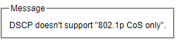
Note here that QoS Setting must be set the Classification Type as Both 802.1p CoS and Diffserv and click Update button first, so that DSCP Mapping will be supported. Otherwise, Error message “DSCP does not support 802.1p CoS only” will be presented.
Rate Control
The users have options to set the Rate Control for each port (Port 2.1, 2.2, …, 4.4) on the managed switch as shown in Figure 2.72. The rate control mechanism will set a limit or maximum data rate which the port can transmit. Moreover, the rate control can be imposed on both directions: the incoming traffic (Ingress) and the outgoing traffic (Egress). However, there are some restrictions on the values that can be set on these two rate control parameters. Here is the summary of the rules for Rate Control settings:
The outgoing (Egress) and incoming (Ingress) values must be set between 0 and 102,400 (for 100 Mbps) or 1,024,000 (for 1000 Mbps).
The value 0 is set to turn off the rate control mechanism.
The values must be integer and multiple of 64 when the transmission rate is less than 1,792 Kbps. For example: 64 Kbps, 128 Kbps, 512 Kbps, and 1,792 Kbps.
The values must be integer multiple of 1,024 when the transmission rate is between 1,792 Kbps and 102,400 Kbps (for 100Mbps) or 106,496 Kbps (for 1000M). Ex: 2,048Kbps, 3,072 Kbps, …,102,400Kbps.
The values must be integer and multiple of 8,192 when transmission rate is greater than 106,496 Kbps.
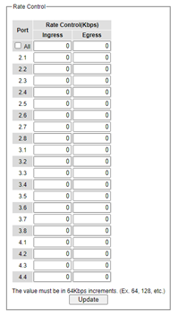
Table 2.17 provides descriptions of rate control setting. Note that after configuring the rate control in each port, please click on the Update button to enable it on the switch.
Table 2.17 Descriptions of Rate Control Settings:
Label |
Description |
Factory Default |
|
|---|---|---|---|
Port (2.1, 2.2, …4.4) |
Port number on the managed switch. |
- |
|
Rate Control (Kbps) |
Ingress |
Sets limits on its transmission rates for the incoming (Ingress) traffic. Note that the unit is inkilo-bits per second (Kbps). |
0 (Disabled) |
Egress |
Sets limits on its transmission rates for the outgoing (Egress)traffic. Note that the unit is inkilo-bits per second (Kbps). |
0 (Disabled) |
Storm Control
This subsection provides the storm control or storm filter features of the managed switch. Storm control prevents traffic on a LAN from being disrupted by ingress traffic of broadcast, multicast, and destination lookup failure (DLF) on a port (2.1, 2.2, … 4.4). Figure 2.73 depicts the Strom Control webpage. The users can impose the same limiting parameters on all ports at the same time by clicking on the box in front of all line and set the storm control data rate under each limiting column (DLF, Multicast, Broadcast). The storm control limiting can also be independently control on each port. Note that the limiting value of 0 means that the storm control is disable and the value must be in multiples of 64kbps. Additional ingress storm traffic will be dropped after the limit has reached. Table 2.18 summarizes the descriptions of storm control. Table 2.19 summarizes the descriptions of limiting parameters for storm control.
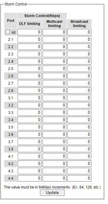
Table 2.18 Descriptions of Storm Control:
Label |
Description |
Factory Default |
|---|---|---|
All |
Enable or Disable the storm control or filter on all ports at the same time. The limiting data rate for each type of storm packets (DLF, Multicast, and Broadcast) can be controlled by changing the number under each column. Note that the value must be in multiples of 64kbps. |
Uncheck and Disable |
Port (2.1, 2.2, … 4.4) |
Set the limiting data rate of storm packets that can be controlled for each Port, which are DLF, Multicast, and Broadcast. Note that the value must be in multiples of 64kbps. See notes below for the detailed description and comparison. |
Disable |
Table 2.19 Descriptions of Limiting Parameters:
Label |
Description |
Factory Default |
|---|---|---|
DLF limiting (Destination Lookup Failure) |
DLF limiting (0~9876480) Kb |
0 (Disable) |
Multicast limiting |
Multicast limiting (0~9876480) Kb |
0 (Disable) |
Broadcast limiting |
Broadcast limiting (0~9876480) Kb |
0(Disable) |
Type of Storm Packets:
DLF: Destination Lookup Failure. The switch will always look for a destination MAC addressin its MAC Table first. In case that a MAC address cannot be found in the Table, which means DLF occurs, the switch will forward the packets to all ports that are in the same LAN.
Multicast: This type of transmission sends messages from one host to multiple hosts. Only those hosts that belong to a specific multicast group will receive it. Network devices that support multicast send only one copy of the information across the network until the delivery path that reaches group members diverges. At these diverging points, multicast packets will be copied and forwarded. This method helps reducing high traffic volumes due to large number of destinations, using network bandwidth efficiently.
Broadcast: Messages are sent to all devices in the network.
Redundancy
Welotec’s industrial managed switch provides full control on redundancy. In this section, the users can select redundancy protocol for each port: either PRP (Parallel Redundancy Protocol) or HSR (High availability Seamless Redundancy). All Redundancy’s setting for each port can be viewed in this section. Figure 2.74 illustrates the Redundancy Setting webpage. The Redundancy section is subdivided into one subsection which is: Setting.
Setting
Both High-availability Seamless Redundancy (HSR) and Parallel Redundancy Protocol (PRP) are the methods of network recovery which provide “zero recovery time” without any packet loss. PRP and HSR are standardized by the IEC 62439-3:2016. Both methods are suitable for applications that require high availability and low switchover time, such as the protection of an electrical substation, or the protection of high-power inverters.
HSR-PRP module is developed to be a part of RSAGS switch. The FPGA device licensed from Flexibilis is used to organize the module. The basic operation of these protocols is that the Ethernet packets are transferred from switch to the FPGA. Then, the FPGA converts these packets into HSR or PRP format before forwarding the packets to two of its redundant ports.
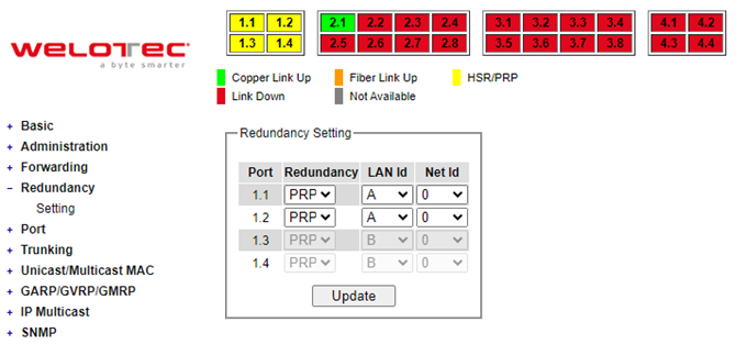
Figure 2.74 shows the dropdown menu for HSR/PRP section on the RSAGS managed switch. User could modify the redundancy type of each port by selecting either HSR or PRP type and choosing the configured LAN ID and Net ID before clicking the update button.
Port-related settings
Welotec’s industrial managed switch provides full control on all its network interfaces. In this section, the users can enable or disable each port and set preferred physical layer mode such as copper or fiber. Moreover, the users will be able to configure negotiation mechanism, data rate (speed), duplexing, and flow control for each port. All port’s status and statistics can be viewed in this section. Figure 2.75 illustrates the Port webpage. The Port section is subdivided into five subsections which are:
Port Setting
Port Status
Mini-GBIC Port Status
Port Statistics
Advanced
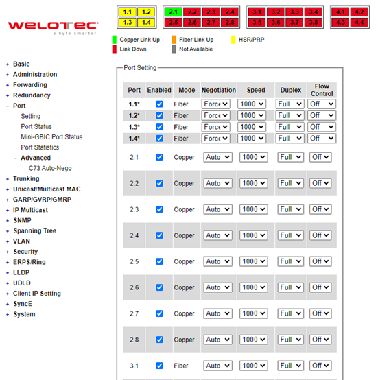
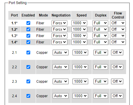
Port Setting
Port Setting webpage is shown in Figure 2.76. The users can control the state of each port by checking on the corresponding Enable box. The possible physical layer connections of each port are listed on the Mode column. In some of Welotec’s managed switches (EH75xx Series), the users can select one of the physical media to be a preferred mode of operation. However, the example in Figure 2.76 is based on RSAGS which does not have a combo port and cannot select preferred mode of operation.
Next on the fourth column of Figure 2.76, for Copper option port 1.1-1.4, user can select only Auto from the dropdown list in the Negotiation mechanism. Port’s speed is unchangeable, and it is set at 1000 Mbps, full duplex, and Flow control is set to off. The setting is more flexible for the user when it is the other Copper port and Fiber option. Here, the users can select from the dropdown list the port’s Negotiation mechanism which can be either Auto or Force. When selecting the Force negotiation, the port’s speed and duplexing will be locked to the settings configured by the users. On the other hand, the Auto negotiation will allow the switch to determine the actual speed and duplexing for that port. Note that the Gigabit Small Form-factor Pluggable (SFP) Port of the EH Series switch is downward compatible with 125/155Mbps Transceivers; however, the speed needs to be set to 100 manually. The Gigabit SFP Port of the RSAGS Series is not downward compatible.
On the fifth column, the transmission Speed of each port can be chosen from the dropdown list which could be 10, 100, or 1000 Mbps. The default speed is set to the highest possible rate in Mbps. Next the port’s duplexing (Duplex) can be either Full duplex or Half duplex. The Half duplex option allows one-way communication at a time, while the Full duplex option allows simultaneous two-way communication.
Each port can set the Flow Control mechanism to either On or Off on the eighth column. This flow control will be useful to avoid packet loss when there is a network congestion. However, the Flow Control setting is Off by default. After configuring the port setting, please click on the Update button to enable any of your new configuration on the switch. Descriptions of port setting options are summarized in Table 2.20.
Table 2.20 Descriptions of Port Settings:
Label |
Description |
Factory Default |
|---|---|---|
Port |
Port number on the managed switch. |
- |
Enable |
Check the box to allow data to be transmitted and received through this port |
All ports are enabled |
Mode |
Copperand/or Fiber modes |
Depend |
Negotiation |
Choose from either Force or Auto. See description in the paragraph above. |
Auto-negotiation is enabled to all ports. |
Speed |
Select either 10, 100, or 1000Mbps |
Highest Speed |
Duplex |
Select either Half or Full Duplex. See description in the paragraph above. |
Full-Duplex |
Flow Control |
Either on or off. The Flow Control mechanism can be enabled (On) to avoid packet loss when congestion occurs. |
Off |
Port Status
The overview of port status on the managed switch can be viewed in this webpage. The users can compare the actual status and the configured options described in previous subsection for each port. The rate control (ingress and egress) can be configured based on the instructions on Section 2.4.2. Figure 2.77 shows the Port Status webpage. Note that the last column also reports the security status whether it is turned on or off on each port, which can be either static security or 802.1x. To check the latest status of all port, click the Refresh button either on the top or the bottom of the webpage.
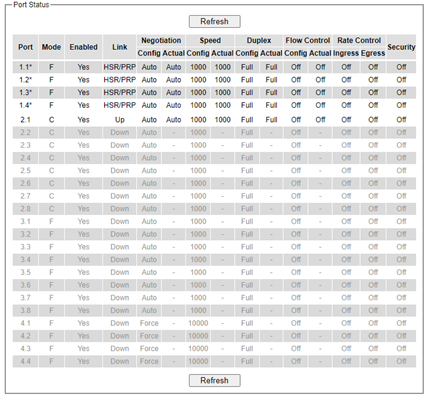
The header in each column and its possible values of the ports’s status are listed here:
Mode (Copper (C) or Fiber (F))
Enable (Yes or No)
Link (Up or Down)
Negotiation (Auto or Force)
Speed (unit: Mbps)
Duplex (Full or Half)
Flow Control (On or Off)
Rate Control (On or Off)
Security (On or Off): Either static security or 802.1x port security is turned on or off.
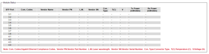
Mini-GBIC Port Status
The Small Form-factor Pluggable (SFP) port is sometimes referred to as a Mini-GBIC (Giga Bitrate Interface Converter). In this subsection, all Mini-GBIC ports status can be shown if supported by the managed switch. Figure 2.78 depicts the Module (or Mini-GBIC Port) Status webpage. Here, the status provides the Ethernet compliance codes, vendor name, vendor part number (PN), laser wavelength (L.W.), vendor serial number (SN), Connection Type, temperature T(C), voltage V, transmitted (Tx) power and received (Rx) power. The link status (up or down) can be viewed in the previous subsection.
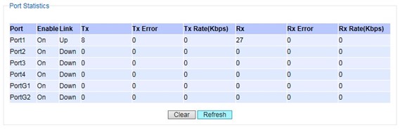
Port Statistics
The Port Statistics are summarized in this webpage as shown in Figure 2.79. The users can use this subsection to help them diagnose the problem such as link quality of each port. The key statistics are the total number of normal (OK) frames, the number of discarded (Error) frames, and the speed of the transmission (Rate in Bps) for both transmitted (Tx) and received (Rx) traffic in each port. To clear or reset all the statistics to zero on this page, click on the Clear button. To obtain the latest statistics on this page, click on the Refresh button.
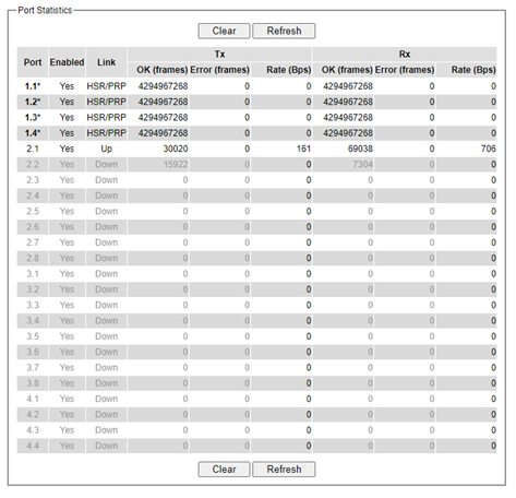
The header in each column and its possible values of the ports’s statistics are listed here:
Enable (Yes or No): The port is enabled (Yes) or disabled (No).
Link (Up or Down): Actual link status of the port.
TxOK (frames): Total number of packets transmitted.
Tx Error (frames): The number of outbound packets which were chosen to be discarded even though no errors have been detected to prevent them from being transmitted.
Tx Rate (Bps): Speed of transmission in Bytes per second.
RxOK (frames): Total number of packets (not including faulty packets) received.
Rx Error (frames): Total number of faulty packets (including Oversize, Undersize, Frame Check Sequence (FCS), Alignment, Jabber and Fragment Errors in packets) received.
Rx Rate (Bps): Receiving speed in Bytes per second.
Advanced
Under the Advanced menu, the users can enable the Blackplane Ethernet Auto-Negotiation based on Clause 73 (C73) of the IEEE 802.3-2008 standard. To enable the C73 Auto-Nego, check the Enabled box and click on the Update button as shown inFigure 2.80.
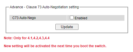
Note: Only for 4.1, 4.2, 4.3, 4.4 New setting will be activated the next time you boot the switch.
Trunking
The managed switch supports Link Trunking, which allows one or more links to be combined as a group of links to form a single logical link with larger capacity. The advantage of this function is that it gives the users more flexibility while setting up network connections. The bandwidth of a logical link can be doubled or tripled. In addition, if one of links in the group is disconnected, the remaining trunked ports can share the traffic within the trunk group. This function creates redundancy for the links, which also implies a higher reliability for network communication. Figure 2.81 shows the Trunking dropdown menu.
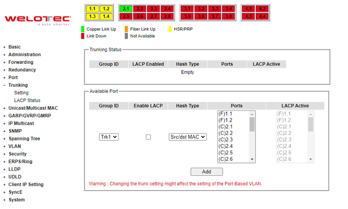
Trunking Setting
In this subsection, the user can create new trunking assignment(s) and remove existing trunking assignment(s). Figure 2.82 illustrates the Trunking Setting webpage. The top part of the page called Trunking Status lists existing trunk(s) which can be removed by pressing the Remove button in the last column. Each line of the trunking provides information about the group of links (Trunk) based on Group ID labeled with Trkx where x is the integer number from 1 to 8. The managed switch can support up to 8 trunk groups. Note that for the difference media types (for example Fast Ethernet, Gigabit Ethernet, and Fiber), port trunking needs to be combined separately. Note that (F) refers to the fiber port, while (C) refers to the copper port. There is a section called Available Port for creating trunking as shown in the lower part of the webpage.
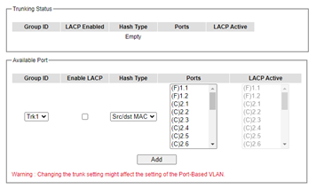
The users have an option to enable Link Aggregation Control Protocol (LACP) which is an IEEE standard (IEEE 802.3ad, IEEE 802.1AX-2008) by checking on the box under the LACP column for each group. LACP allows the managed switch to negotiate an automatic bundling of links by sending LACP packets to the LACP partner or another device thatis directly connected to the managed switch and implements LACP. The LACP packets will be sent within a multicast group MAC address. If LACP finds a device on the other end of the link that also has LACP enabled, it will also independently send packets along the same links enabling the two units to detect multiple links between themselves and then combine them into a single logical link. During the detection period LACP packets are transmitted every second. Subsequently, keep alive mechanism for link membership will be sent periodically. Each port in the group can also operate in either LACP active or LACP passive modes. The LACP active mode means that the port will enable LACP unconditionally, while LACP passive mode means that the port will enable LACP only when an LACP partner is detected. Note that in active mode LACPport will always send LACP packets along the configured links. In passive mode however, LACP port acts as “speak when spoken to”, and therefore can be used as a way of controlling accidental loops (if the other device is in active mode). To enable trunking over multiple ports, the users can follow the steps below:
Step 1: Select Trkx (x = 1 to 8) from Group IDdropdown list.
Step 2: Choose whether to enable LACP (IEEE standard, Link Aggregation Control Protocol).
Step 3: Select the Hash Type from the dropdown list.
Step 4: Select specific ports to be in this trunk group from the text box.
Step 5: Select specific ports in this trunk group to be LACP active.
Step 6: Click Apply button to set the configuration on the managed switch.
Descriptions of trunking settings are summarized in Table 2.21.
Table 2.21 Descriptions of Trunking Settings:
Label |
Description |
|---|---|
Group ID |
Up to 8 trunk groupscan be created: Trk1~Trk8. Note that it is not possible to mix Fast Ethernet ports and Gigabit Ethernet ports into the same trunk group. |
LACP |
Enable/Disable LACP (Link Aggregation Control Protocol). Brief explanation of LACP is discussed in previous paragraph. |
Hash Type |
The hash result determines which port to use for a specific frame. The available hash options are: Src MAC, Dst MAC, Src/dst MAC, Src IP, Dst IP, and Src/dst IP. |
Ports |
Specify the member ports for this trunking group. Please hold Ctrl (control) key to select more than one port at a time. |
LACP Active |
Specify which ports within the group should bein LACP Active mode. The ports that are not selected will be in LACP Passive mode. |
Apply |
Click Apply button to confirm the changes. |
Remove |
Click this button to remove any existing trunking group. |
LACP Status
Figure 2.83 lists the current switch’s trunking information. At the top of the page, the status of LACP on the managed switchis reported whether it is enabled or disabled. Next, the users can also specify the system priority here. LACP uses the system priority with the switch’s MAC address to form the system ID and also during negotiation with its LACP partner. The LACP system ID is the combination of the LACP system priority value (defined in this webpage) and the MAC address of the managed switch. The system priority determines which managed switch makes the decisions on ports that will be bundled into a logical link. The lowest value determines who has higher priority and is in charge. The table of LACP status provides information per port which are port number, status of LACP, group ID, and LACP partner. Table 2.22 explains the descriptions of LACP status.
To change system priority, enter the desired number in the number box behind the system priority field and then click Update button. To obtain the latest status of the LACP, click on the Refresh button.
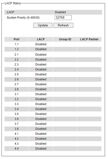
Table 2.22 Descriptions of LACP Status
Label |
Description |
Factory Default |
|---|---|---|
System Priority |
Indicate the system priority value of the managed switch in the range of 1 ~ 65535. System priority is used during the negotiation with other systems. System priority and switch’s MAC address is used to form a system ID. Note that a higher number means a lower priority. |
32768 |
Group ID |
Show which trunk group that this port belongs to. |
- |
LACP |
Disabled: LACP is disabled. Passive: LACP will only passively respond to LACP requests. Active: LACP will be actively searching for LACP Partner. |
- |
LACP Partner |
Indicates whether a LACP Partner can be located on the other side. |
- |
Unicast/Multicast MAC
The managed switch is a network device which operate at the OSI layer 2 or medium access control (MAC) layer. It forwards frames of OSI layer 2 based on the MAC addresses. Generally, the layer 2 switch will learn about the destination MAC addresses of the end devices which are connected to the switch over time based on the exchanged traffic. For instance, in the beginning if the switch does not know which port a destination MAC address is, it will forward or broadcast a frame to all its ports and wait for a response from end device connected to one of the ports. This way the switch will learn of the MAC address and corresponding port number. Later, the switch will forward the frame to the destination port only thus saving the traffic on other ports.
The managed switch typically maintains the learned MAC addresses in its memory which is usually called a MAC Address table. In this section, the managed switch allows the users to control the MAC Address table by adding static MAC addresses into the table or filtering certain MAC addresses so that they will not be forwarded by the managed switch. Welotec’s manage switch also provides the users with the ability to set the MAC address age-out manually. Note that the age-out period is a duration of time that a learned MAC address will be maintained in the MAC address table before it was removed to save the memory.
The MAC addresses that can be managed by the switch can be both Unicast and Multicast MAC addresses. This section will briefly explain the concept of Unicast and Multicast forwarding as well as their benefits. Please see Figure 2.84 for illustrations of the Unicast versus the Multicast concept.
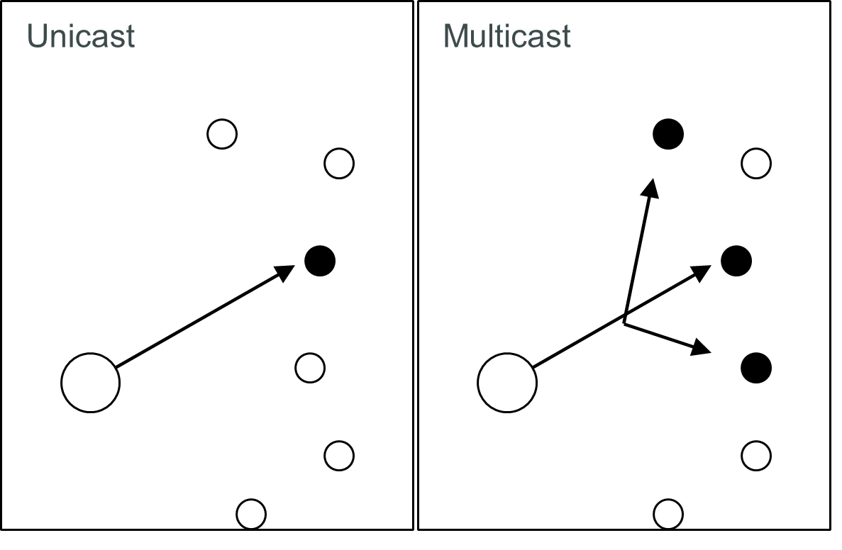
Unicast: This type of transmission sends messages to a single network destination identified by a unique MAC address. This method is simple with one source and one destination.
Multicast: This type of transmission is more complicated. It sends messages from one source to multiple destinations. Only those destinations or hosts that belong to a specific multicast group will receive the multicast packets. In addition, networks that support multicast send only one copy of the information across the network until the delivery path that reaches group members diverges. At these diverging points, multicast packets will be copied and forwarded. This method can manage high volume traffic with different destinations while using network bandwidth efficiently. Multicast filtering improves the performance of networks that carry multicast traffic.
Figure 2.85 shows the Unicast/Multicast dropdown menu which allows the users to manage and view the status of MAC address table.

Add Static MAC
The managed switch allows the users to manually add static MAC addresses into its memory. The static MAC addresses will enable the managed switch to forward the traffic based on the MAC addresses in its memory to the destination port with specific virtual local area network (VLAN) identification (VID). Following the simple steps here to add a static MAC address.
Step 1: Enter a MAC Address which can be either Unicast or Multicast MAC Address.
Step 2: Specify VLAN ID (VID).
Step 3: Select the ports to apply this static MAC address. Use Ctrl-key to add more than one port. Step 4: Click on Add button.
Figure 2.86 depicts the Add Unicast/Multicast MAC webpage. There is an example of a table of static MAC address in the upper part of the webpage where the last column of the table has Remove buttons for each entry. The users can remove any existing static MAC address by clicking on the Remove button. The lower part of the webpage is where the user can enter a new static MAC address along with its VLAN ID (VID) as outlined by the procedure above. Table 2.23 summarizes the fields in this Add Static MAC webpage.
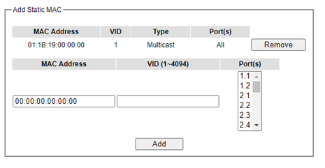
Table 2.23 Description on fields in Add Static MAC Webpage:
Label |
Description |
|---|---|
MAC address |
Enter a MAC address manually. |
VID |
Specify VLAN ID that this static MAC belongs to (1 - 4096). |
Type |
Multicast or Unicast MAC address |
Port(s) |
Define which ports toapply this static MAC address. |
Add |
Confirm and add the MAC addressby clicking on this button. |
Remove |
Click on this button to remove existing static MAC addressinthe table. |
Black-List MAC
As discussed earlier, the managed switch also allows users to set MAC filtering manually. Figure 2.87 shows the Black-List MAC webpage. The upper part of the page is the table of existing filtered MAC address where the users can remove the filter by clicking on the Remove button on each entry. The lower part of the page is where a new source MAC address that the users would like to filter can be entered into the MAC filtering table (black list). Table 2.24 summarizes the fields in the MAC Filter webpage.
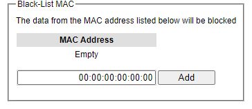
Table 2.24 Descriptions of MAC Filtering Webpage:
Label |
Description |
|---|---|
MAC Address |
Enter MAC address to be black-listed or filtered manually. |
Remove |
Remove the corresponding entry in MAC filtering table. |
Add |
Add a MAC addresses to the MAC filtering table. |
MAC Aging Time
This function allows users to set MAC address age-out or aging time manually as shown in Figure 2.88. The users can specify the Age-out Time between 0 and 600 seconds in the following field. Note that the default value of ageout time is 300 seconds. In the managed switch, a MAC address table is stored in the memory to map a MAC address and a port number to forward frames. The aging time is the duration of time to keep MAC addresses in the MAC addresstable. For a longer aging time, the learned MAC address will stay in the memory longer. As a result, the switch will be able to forward the frames to a specific port quickly instead of forwarding to all the ports to prevent frame flooding. A shorter aging time will allow the switch to free up the old MAC addresses in the table to learn new MAC addresses. This will be useful when there are large number of MAC addresses (or end devices) in the network and when the traffic between any two end devices is short-lived.
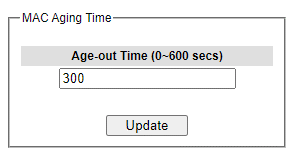
MAC Table
Information of current Unicast and Multicast MAC addresses in the memory (MAC Table) of the managed switch is displayedin this webpage as shown inFigure 2.89. The list of Unicast MAC addressesis shown first and follows by the list of Multicast MAC addresses. If there are more entries to be displayed, the users can click on the Next Page button to see other entries. The users also have an option to clear dynamic entries in the MAC address table by clicking on the Clear Dynamic Entries button at the bottom of the webpage. The descriptions of the MAC Address table are summarized in Table 2.25.
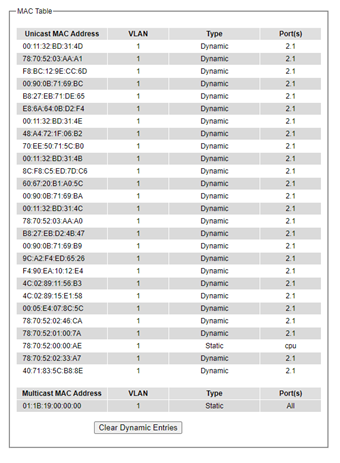
Note: The static multicast address can be set from “Add Static MAC” (Section 2.8.1) in “Unicast/Multicast MAC” (Section 2.8) or from “Static IP Multicast” (Section 2.10.2) in “IP multicast” (Section 2.10).
Table 2.25 Descriptions of MAC Address Table:
Label |
Description |
|---|---|
Unicast/Multicast MAC |
Display MAC address. |
VLAN |
Display VLAN ID. |
Type |
Display whether the MAC address is dynamic or static. Note that dynamic is the address that is learned automatically, while static is the address that is entered by the users. |
Ports |
Display which port that this MAC address belongs to. |
Clear Dynamic Entries |
Clear all Dynamic MAC addressesby clicking this button. |
Next Page |
Clicking on this button to continue to the next page when there are more MACs available. |
GARP/GVRP/GMRP
This page includes three options, GARP, GVRP, and GMRP settings as shown in Figure 2.90. Main concept of all three protocols is to eliminate unnecessary network traffic by preventing transmission/retransmission to unregistered users. These functions are enabled by default. They can only be disabled if no MAC addresses are added in the multicast group table. GARP: Generic Attribute Registration Protocol, previously called Address Registration Protocol, is a LAN protocol that defines procedures by which end stations and switches can register and de-register attributes, such as network identifiers or addresses with each other. Every end station and switch thus have a record, or list, of all the other end stations and switches that can be reached at a given time. Specific rules are used to modify set of participants in the network topology, or so-called reachability tree. GVRP: GARP VLAN Registration Protocol. GVRP is like GARP but work with VLAN instead of other network identifiers. It provides a method to exchange VLAN configuration information with other devices and conforms to IEEE 802.1Q. GMRP: GARP Multicast Registration Protocol provides a mechanism that allows bridges (or switches in this case) and end stations to dynamically register group membership information with the MACs of bridges (switches) attached to the same LAN segment and for that information to be disseminated across all bridges (switches) in the Bridged (switched) LAN that supports extend filtering services. GMRP provides a constrained multicast flooding facility like IGMP snooping. The difference is that IGMP is IP-based while GMRP is MAC-based.
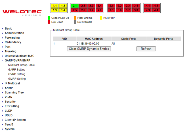
Multicast Group Table
In this subsection, the list of MAC addresses which were dynamically registered by GMRP into the Multicast Group Table can be viewed. The multicast group table in Figure 2.91 displays the following information for each MAC. Address: VLAN ID (VID), Static Port(s), and GMRP Dynamic Port(s). The user can clear the table by clicking on the Clear GMRP Dynamic Entries button or obtain the latest update on the table by clicking on the Refresh button.
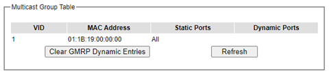
GARP Setting
Figure 2.92 shows GARP Setting webpage where different Timers (Join, Leave, and Leave All) can be set. All devices that are exchanging attributes must set these timers to the same values. Note that the GARP Timer values are in multiple of 10 milliseconds. Table 2.26 summarized the descriptions and values of all Timers for GARP setting. Please click the Update button after setting your new values.
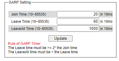
Table 2.26 Descriptions of GARP Timer Settings:
Label |
Description |
Factory Default |
|---|---|---|
Join Timer |
Indicates the GARP Join timer, in 0 ~ 65535 seconds. |
200 milliseconds |
Leave Timer |
Indicates the GARP Leave timer, in 0 ~ 65535 seconds. |
600 milliseconds |
LeaveAll Timer |
Indicates the GARP Leave All timer, in 0 ~ 65535 seconds. |
10000 ms or 10 s |
GVRP Setting
In this section, GVRP can be enabled on the switchand then it can be enabled for all ports or specific port(s) and trunking group(s). The multicast IP address with designated VLAN ID can be accessed from each port. Figure 2.93 and Figure 2.94 illustrate GVRP Setting and Statistics. When GVRP is enabled, the switch which is an end node of a network needs to add static VLANs locally. Other switches can dynamically learn the rest of the VLANs configured elsewhere in the network via GVRP.
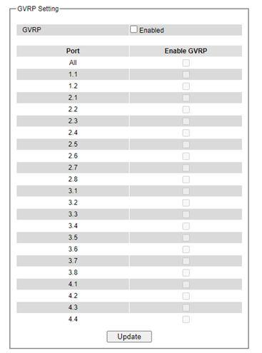
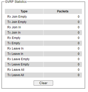
To enable GVRP in Figure 2.93, check the Enabled’s box and then select the desired port(s) by flagging the corresponding checkbox(es). Please click Update button to save the change to the switch. Figure 2.94 provides summarized statistics on the packet count of GVRP based on the following packet types: Rx Join Empty, Tx Join Empty, Rx Join In, Tx Join In, Rx Empty, Tx Empty, Rx Leave In, Tx Leave In, Rx Leave Empty, Tx Leave Empty, Rx Leave All, and Tx Leave All. To clear the statistics on this table, please click on the Clear button at the bottom of the table. Table 2.27 describes the GVRP setting’s options.
Table 2.27 GVRP Setting Descriptions:
Label |
Description |
Factory Default |
|---|---|---|
GVRP |
Enables or disables GVRP protocol. Enables GVRP, the switch must be in 802.1q VLAN mode. |
Disabled |
Port |
Enables or disables GVRP on each port. If users have already defined trunking group (e.g. Trk1), it can also be selected to be enabled. If you check the All Port’s box, all ports will be enabled. |
All ports are disabled |
Clear Statistics |
Clears all GVRP statistics counts. |
Clears the record |
GMRP Setting
The users can use this subsection to enable GMRP and enable GMRP for all ports or specified port(s) and trunking group(s) as shown in Figure 2.95. To enable GMRP in Figure 2.95, check the Enabled’s box and then select the desired port(s) by flagging the corresponding checkbox(es). Please click Update button to save the change to the switch.
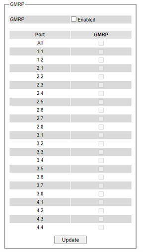
The GMRP Statistics can also be viewed on the bottom of this page as shown in Figure 2.96. The GMRP Statistics provides summarized statistics on the packet count of GMRP based on the following packet types: Rx Join Empty, Tx Join Empty, Rx Join In, Tx Join In, Rx Empty, Tx Empty, Rx Leave In, Tx Leave In, Rx Leave Empty, Tx Leave Empty, Rx Leave All, and Tx Leave All. To clear the statistics on this table, please click on the Clear button at the bottom of the table. Table 2.28 briefly describes GMRP setting and statistics.
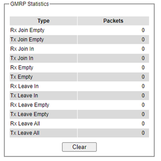
Table 2.28 Descriptions of GMRP Settings and Statistics:
Label |
Description |
Factory Default |
|---|---|---|
GVRP |
Enables or disables GVRP protocol. Enables GVRP, the switch must be in 802.1q VLAN mode. |
Disabled |
Port |
Enables or disables GVRP on each port. If users have already defined trunking group (e.g. Trk1), it can also be selected to be enabled. If you check the All Port’s box, all ports will be enabled. |
All ports are disabled |
Clear Statistics |
Clears all GVRP statistics counts. |
Clears the record |
IP Multicast
The managed switch supports Internet Group Management Protocol (IGMP) which is a communication protocol used on IP version 4 networks to establish multicast group memberships among switches in the network. IGMP is an integral part of IPv4 multicast. It operates above the network layer of OSI model. One of the most important features related to this protocol is IGMP snooping, which is supported by the managed switch and greatly strengthens network functionality. The IGMP snooping is a process of “listening” to IGMP network traffic. By listening to conversations between different devices, it maintains a map of links and IP multicast streams. This means that multicast traffic may be filtered from the links of the managed switch which do not need them. Therefore, IGMP snooping enables the managed switch to only forward multicast traffic to the links that have requested it. This section contains three submenus as shown in Figure 2.97 which are:
IGMP
Static IP Multicast
MLD
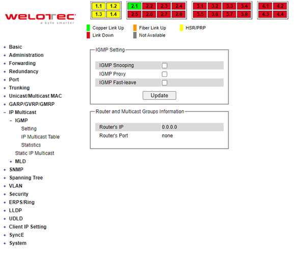
IGMP
The IGMP (Internet Group Management Protocol) submenu is further divided into three options which are: Setting, IP Multicast Table, and Statistics. Figure 2.98 shows the three options under the IGMP submenu.
IGMP Settings
This webpage allows the users to set IGMP features on the managed switch as shown in Figure 2.99. There are three features that can be enabled: IGMP Snooping, IGMP Proxy, and IGMP Fast-leave. After checking the desired feature’s boxes, please click on the Update button to allow the options to take effect. The lower part of the page lists Router and Multicast Groups Information which are router’s IP and port information. Table 2.29 summarizes the descriptions of IGMP’s Settings.
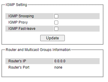
Table 2.29 Descriptions of IGMP’s Settings:
Label |
Description |
Factory Default |
|---|---|---|
IGMP Snooping |
Check the box to enable IGMP snooping. |
Disabled |
IGMP Proxy |
Check the box to enable IGMP proxy. See note below. |
Disabled |
IGMPFast-leave |
Check the box to enable IGMP Fast-leave. See note below. |
Disabled |
Router’s IP |
Display the multicast router’s IP address. |
- |
Router’s Port |
Display the port that is connected to multicast router. |
- |
*Note: IGMP Proxy works as an intermediate server, as shown in Figure 2.100. When it receives a membership query message from the router, it sends a membership report message to the router port. When it receives a membership report message from a computer in a new multicast group, it sends a membership report message back to the router port. When it receives a leave group message from a computer which is the only one in the group, it sends a leave group message to the router port and removes the computer from multicast group. Proxy is like a middleman that handles information about multicast group in between routers and computers.
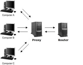
IGMP Fast-leave: When a leave group message is received, the ports in the group will be immediately removed from the IP multicast entry.
IGMP IP Multicast Table
This webpage provides information about IGMP membership table and IP multicast table. Figure 2.101 depicts the IGMP’s IP Multicast Table webpage. The upper table is an IGMP membership table, and the lower table is IP multicast table which contain both static configured IP multicast addresses and dynamically joined IP multicast addresses. The static configured port is manually added by the users, while the dynamically joined port is added by the managed switch’s IGMP snooping feature. To get the latest update information on each table please click on the Refresh button.
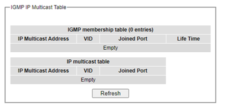
Figure 2.102 shows examples of IGMP membership table and IP multicast table. Note that the display format in Figure 2.102 is from an early version of managed switch firmware which may have a slightly different display format from Figure 2.101. These tables are based on the information in the memory of the managed switch. The IGMP membership table contains IP Multicast Address, VLAN ID (VID), Joined Port (port number) and Lifetime. Note that the Lifetime is in the unit of second. The IP multicast table has only IP Multicast Address, VLAN ID (VID), and Joined Port. Note that the joined port can be labelled with (S)or (D) which refers to as Static Configured or Dynamically Joined, respectively.
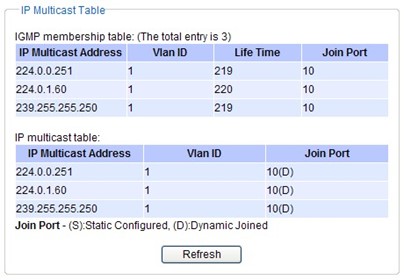
IGMP Statistics
This webpage provides information about IGMP statistics as shown in Figure 2.103. The users can view the number of IGMP packets in different categories: Rx Total, Rx Valid, Rx Invalid, Rx General Queries, Tx General Queries, Rx Group-Specific Queries, Tx Group-Specific Queries, Rx Leaves, Tx Leaves, Rx Reports, Tx Reports, and Rx Others. The users can reset the numbers in all categories by clicking on the Clear button.
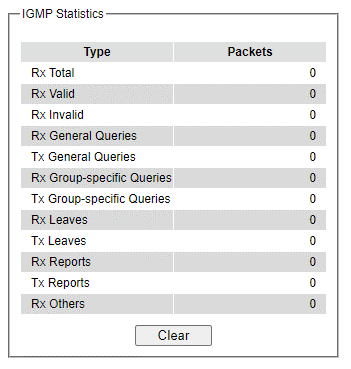
Example of IGMP statistics are shown in Figure 2.104. Note that the display format in Figure 2.104 is from an early version of managed switch firmware which may have a slightly different display format from Figure 2.103. It shows the statistical values of IGMP packets which the managed switch received and transmitted over time. Table 2.30 summarizes the descriptions of the IGMP statistics.
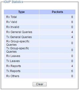
Table 2.30 Descriptions of IGMP Statistics:
Statistics Label |
Description |
Factory Default |
|---|---|---|
Rx Total |
Total number of IGMP packets received by the managed switch |
- |
Rx Valid |
Number of valid IGMP packets received by the managed switch |
- |
Rx Invalid |
Number of invalid IGMP packets received by the managed switch |
- |
Rx General Queries |
Number of IGMP’s Membership General Query packets received by the managed switch |
- |
Tx General Queries |
Number of IGMP’s Membership General Query packets transmitted by the managed switch |
- |
Rx Group Specific Queries |
Number of IGMP’s Membership Group Specific Query packets received by the managed switch |
- |
Tx Group Specific Queries |
Number of IGMP’s Membership Group Specific Query packets transmitted by the managed switch |
- |
Rx Leaves |
Number of IGMP’s Leave Group packets received by the managed switch |
- |
Tx Leaves |
Number of IGMP’s Leave Group packets transmitted by the managed switch |
- |
Rx Reports |
Number of IGMP’s Membership Report packet received by the managed switch |
- |
Tx Reports |
Number of IGMP’s Membership Report packet transmitted by the man. switch |
- |
Rx Others |
Number of IGMP’s other packets received by the managed switch |
- |
Static IP Multicast
This subsection allows the users to manually add new or remove existing static IP multicast and the joined port(s). Figure 2.105 shows the Static IP Multicast webpage where the upper part of the page is a table of existing IP Multicast Address entries, and the lower part of the page contains the fields for adding new IP Multicast Address entry to the table. The users are required to supply the IP Multicast Address, VLAN ID (VID), and the lists of the port numbers which will join the static IP multicasting group (joined port).
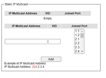
An example of an entry of IP multicast group is shown in Figure 2.106 where there is an existing IP Multicast Address of 224.2.3.4 which belongs to VLAN 1 and has port number 2, 3, and 6 in the group. The following procedures outline how to add a new IP multicast group. For example, an IP multicast group address is 224.1.1.1 and the joining ports are Port1, Port2 and Port5 with VLAN = 1.
First, the users should enter the IP = 224.1.1.1 in the IP Multicast Address column.
Then, the users should enter the VLAN ID = 1 in the VLAN ID (VID) column.
Then, while holding the “Ctrl” key on the keyboard, click on all corresponding port numbers under the Join Port column (Port1, Port2, and Port5 in this example) to select which port(s) will join in the IP multicast group.
Finally, click on the “Add” button. The IP address is then added as it shows on Figure 2.106.
To remove an existing static IP multicast address from the table, click the “Remove” button of that entry.
These procedures are like the procedures for adding or removing the Unicast/Multicast MAC address explained in Section 2.8.1. The only difference is that the IP multicast address has the form of 224.XX.XX.XX. Note that IPv4 multicast address (Class D) is in between 224.0.0.0 and 239.255.255.255.
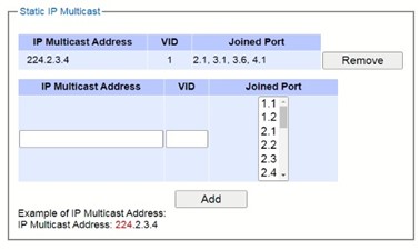
MLD
Multicast Listener Discovery (MLD) is a protocol used by RSAGS in Internet Protocol Version 6 (IPv6) network to discover nodes on its directly attached interfaces that would like to receive multicast packets. These neighboring nodes are called multicast listenters.MLD is embedded in ICMPv6 (Internet Control Message Protocol Version 6) as a part of IPv6 protocol suit. It is like Internet Group Management Protocol (IGMP) in IPv4 as described in Section 2.10.1 above. The protocol speficifically discovers which multicast addresses are of interest to its neighboring nodes. For IPv6, the address range of FF00::/8 are reserved for multicast addresses. Then, MLD provides this information to the active multicast routing protocol on the RSAGS so that multicast packets can be delivered to all relevant interfaces and eventually to the subscribed multicast listeners. Note that MLD is an asymmetric protocol in which it specifies different behaviours for multicast liteners and for routers (or managed switches in our case). The MLD section, which is under the IP Multicast menu, contains three submenus which are Setting, IPv6 Multicast Table, and Statistics as shown inFigure 2.107.
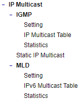
Typically, MLD device can be classified as one of the follows: a querier, a snooper, or a proxy. An MLD querier is a device that coordinate multicast streams and MLD membership information. The MLD querier can generate membership query message to check which nodes are group members. It can process membership reports and leave messages. An MLD snooper is a device that spies on MLD messages to create flow efficiencies by allowing only subscribed interfaces to receive multicast packets. The MLD snooper can decide on the best path to send multicast packets at Layer 2; however, it cannot alter those packets or generate its own MLD messages. An MLD proxy is a device that passes membership reports upstream towards a source in anoter subnet. On the downstream, the MLD proxy will forward multicast packets and queries towards one or more IP subnets.
MLD Setting
The MLD’s Setting webpage as shown in Figure 2.108. To configure the MLD on RSAGS, the users need to configure a VLAN in the second box of the webpage called MLD VLAN Setting first. To configure the options under the MLD VLAN Setting. First, select a VLAN ID from the drop-down list of VLAN. This VLAN will be configured with the MLD snooping function. Second, the user can enable or disable MLD snooping’s Fast Done function by checking the box behind this option. This function will immediately remove the membership of a multicast listener when the switch received an MLD done message. Third, the MLD Snooping function can be enabled or disabled for the selected VLAN by checking the box behind the Snooping option.
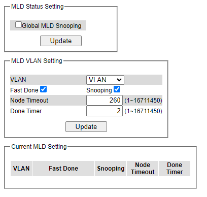
Fourth, the user can specify the amount of time that a node on a port will no longer be considered as a multicast listener. This is called Node Timeout. The default value for Node Timeout is 260 seconds. Fifth, the user can specify the amount of time that a multicast group will remain in the switch after the switch receives a done message of the multicast group without receiving a node listener report. This is called Done Timer. The default value for Done Timer is 2 seconds. Finally, clicking on the Update button to update the configuration of MLD on the selected VLAN ID. The entry of the configured VLAN should be listed in the next part of the webpage.
After setting the VLAN in the step above, the user can enable the Global MLD Snooping option inside the MLD Status Setting box. Then, click Update button to enable the MLD protocol on RSAGS. Note that the MLD snooping is the key to efficient multicast traffic flow in a Layer 2 network of RSAGS managed switch. If no MLD VLAN Setting was done on any VLAN, the user will encounter an error message as show in Figure 2.109.
The current VLANs with MLD setting are listed in the last part of the webpage under the Current MLD Setting box. The setting is summarized as a table with all the options associated with VLAN ID. To remove any entry of the MLD setting, the user can click on the Delete button for that entry.
MLD IPv6 Multicast Table
This webpage provides information about IPv6 Multicast Table and MLD membership table. Figure 2.110 shows the MLD’s IPv6 Multicast Table webpage. The table inside the box is an MLD membership table which contains entries of MLD memberships. Each entry consists of Port Listener, VLAN (VLAN ID), Multicast group, MAC address, Reports, and Lifetime columns. The Multicast group column shows the IPv6 address of the multicast group in each entry. The MAC address column shows the corresponding MAC address of the multicast group in that entry. The Reports column displays the number of group reports for that multicast group. The Port Listener column lists the Port number for each entry. To get the latest update information on each table please click on the Refresh button.
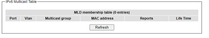
MLD’s Statistics
This webpage provides information about MLD’s statistics as shown in Figure 2.111, which is like the IGMP statistics. The users can view the number of MLD packets in different categories: Rx Total, Rx Valid, Rx Invalid, Rx General Queries, Tx General Queries, Rx Group-Specific Queries, Tx Group-Specific Queries, Rx Leaves, Tx Leaves, Rx Reports, Tx Reports, and Rx Others. The users can reset the numbers in all categories by clicking on the Clear button. Table 2.31 summarizes the descriptions of the IGMP statistics.
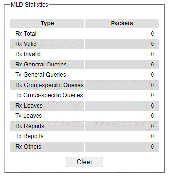
Table 2.31 Descriptions of MLD’s Statistics:
Statistics Label |
Description |
Factory Default |
|---|---|---|
Rx Total |
Total number of MLD packets received by the managed switch |
- |
Rx Valid |
Number of valid MLD packets received by the managed switch |
- |
Rx Invalid |
Number of invalid MLD packets received by the managed switch |
- |
Rx General Queries |
Number of MLD’s Membership General Query packets received by the managed switch |
- |
Tx General Queries |
Number of MLD’s Membership General Query packets transmitted by the managed switch |
- |
Rx Group Specific Queries |
Number of MLD’s Membership Group Specific Query packets received by the managed switch |
- |
Tx Group Specific Queries |
Number of MLD’s Membership Group Specific Query packets transmitted by the managed switch |
- |
Rx Leaves |
Number of MLD’s Leave Group packets received by the managed switch |
- |
Tx Leaves |
Number of MLD’s Leave Group packets transmitted by the managed switch |
- |
Rx Reports |
Number of MLD’s Membership Report packet received by the managed switch |
- |
Tx Reports |
Number of MLD’s Membership Report packet transmitted by the managed switch |
- |
Rx Others |
Number of MLD’s other packets received by the managed switch |
- |
SNMP
Simple Network Management Protocol (SNMP) is a protocol for managing devices on IP networks. It exposes management data in the form of variables on the managed systems which describe the system configuration. These variables can then be queried or defined by the users. The SNMP is used by network management system or third-party software to monitor devices such as managed switches in a network to retrieve network status information and to configure network parameters. The Welotec’s managed switch support SNMP and can be configured in this section. The SNMP setting has four categories, and its dropdown menu is shown in Figure 2.112, which are:
SNMP Agent
SNMP V1/V2c Community Setting
SNMP Trap Setting
SNMP V3 Authentication (Auth.) Setting
SNMP Trap Event Setting
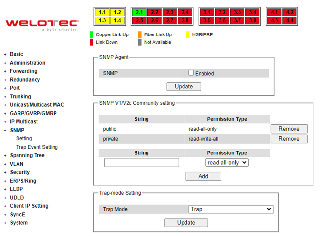
SNMP Agent
To enable SNMP agent on the managed switch, please check the Enabled box and click Update button as shown in Figure 2.113. The SNMP version 1 (V1), version 2c (V2c) and version 3 are supported by Welotec’s managed switches as summarized in Table 2.32. Basically, SNMPV1 and SNMP V2c have simple community string-based authentication protocol for their security mechanism, while SNMP V3 is improved with cryptographic security.
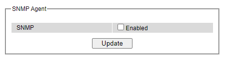
Table 2.32 Description of SNMP Setting:
Label |
Description |
Factory Default |
|---|---|---|
SNMP |
Check the box to enable SNMP V1/V2c/V3. |
Disabled |
SNMP V1/V2c Community Setting
The managed switch supports SNMP V1, V2c, and V3. SNMP V1 and SNMP V2c use a community string matching for authentication. This authentication will allow network management software to access the information or data objects defined by Management Information Bases (MIBs) on the managed switch. Note that this simple authentication is considered a weak security mechanism. It is recommended to use SNMP V3, if possible. There are two levels of authentications or permission type in EHG75XX series, which are read-all-only or read-write-all. For example, in our default setting as shown in Figure 2.114, an SNMP agent, which is a network management software module residing on the managed switch, can access all objects with read-all-only permissions using the string public. Another setting example is that the string private has permission of read write-all.
This community string option allows the users to set a community string for authentication or remove existing community string from the list by clicking on the Remove button at the end of each community string item. The users can specify the string names on the String field and the type of permissions from the dropdown list as shown in Figure 2.114. Table 2.33 briefly provides descriptions of SNMP’s community string setting.
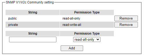
Table 2.33 Descriptions of Community String Settings:
Label |
Description |
Factory Default |
|---|---|---|
(Community) Strings |
Define name of strings for authentication. Max. 15 Characters. |
Public (read-all-only) Private (read-write-all) |
Permission Type |
Choose a type from the dropdown list: read-all only and read-write-all. See notes below for a briefed explanation. |
- |
*Note:
Read-all-only: permission to read OID 1 Sub Tree.
Read-write-all: permission to read/write OID 1 Sub Tree.
SNMP Trap Setting
The managed switch provides a trap function that allows switch to send notification to agents with SNMP traps or inform. The notifications are based on the status changes of the switch such as link up, link down, warm start, and cold start. For inform mode, after sending SNMP inform requests, switch will resends inform request if it does not receive response within 10 seconds. The switch will try re-send three times.
SNMPv2 Trap
This option allows users to configure SNMP Trap Setting by setting the destination IP Address of the Trap server, Port Number of the Trap server, and Community String for authentication. Figure 2.115 shows these Tap Setting’s options. The first line enables the users to select the Trap Mode which can be either Trap or Inform. Please click on the Update button after selecting the desired Trap Mode. After entering all required fields for Trap Setting in the last line, please click on the Add button. Table 2.34 summarizes the descriptions of trap receiver settings.
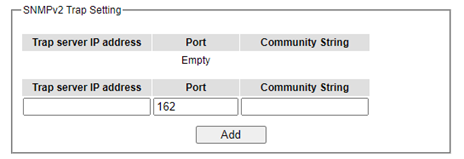
Table 2.34 Descriptions of SNMPv2 Trap Setting:
Label |
Description |
Factory Default |
|---|---|---|
Trap Mode |
Choose between Trap and Inform |
Trap |
Trap server IP address |
Enter the IP address of your Trap Server. |
NULL |
Port |
Enter the trap Server service port. |
162 |
Community String |
Enter the community string for authentication. Max. 15 characters. |
NULL |
SNMPv3 Trap
SNMPv3 use the User-based Security Model (USM) for message security and the View-based Access Control Model (VACM) for access control.
SNMPv3 security model contains authentication and encrypting: a. Authentication is used to ensure that traps are read by specific recipient. A special key is shared between the specific recipient and used to receive the message. b. The payload of the SNMP message will be encrypted to ensure that it cannot be read by unauthorized user.
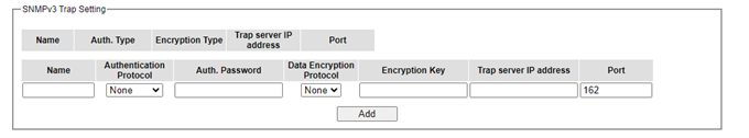
Table 2.35 Descriptions of SNMPv3 Trap Setting:
Label |
Description |
Factory Default |
|---|---|---|
Name |
Configure SNMPv3 trap authentication username |
NULL |
Authentication Protocol |
Select SNMPv3 trap authentication protocol options, the managed switch support below protocol type: None |
NONE |
Auth. Password |
Configure SNMPv3 trap authentication password |
NULL |
Data Encryption Protocol |
Configure SNMPv3 trap data encryption protocol, the managed switch support below type: None |
NONE |
Encryption Key |
Configure SNMPv3 trap encryption key |
NULL |
Trap server IP address |
Configure SNMPv3 trap server ip address |
NULL |
Port |
Configure SNMPv3 trap UDP port number |
162 |
SNMPv3 Auth. Setting
As mentioned earlier, SNMP V3 is a more secure SNMP protocol. In this part, the users will be able to set a password and an encryption key to enhance the data security. When choosing this option, the users can configure SNMP V3’s authentication and encryption. MD5 (Message-Digest algorithm 5) is used for authentication password and DES (Data Encryption Standard) is used for data encryption algorithm. Figure 2.117 shows the SNMP V3 Authentication Setting’ options. The users can view existing SNMP V3 users’ setting on the upper table where it provides information about username, authentication type, and data encryption. The users have an option to remove existing SNMP V3 user by clicking on the Remove button in the last column of each entry. To add a new SNMP V3 user, the users must select the username from the dropdown list which can be either Admin or User. Then, the authentication password with a maximum length of 31 characters must be entered in the Auth. Password field and re-entered again in the Confirmed Password field. Note that if no password is provided, there will be no authentication for SNMP V3. Finally, the encryption key with a maximum length of 31 characters can be entered in the Encryption Key and re-entered again in Confirmed Key field. After filling all the required fields, please click on Add button to update the information on the managed switch. Table 2.36 lists the descriptions of SNMP V3 settings.
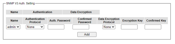
Table 2.36 Descriptions of SNMPv3 Settings:
Label |
Description |
Factory Default |
|---|---|---|
Name |
Choose from one of the following options: Admin: Administration level. User: Normal user level. |
Admin |
Authentication Protocol |
Choose used authentication procotol type, the mamanged switch support below protocol types: None |
NONE |
Auth. (Authentication) Password |
Set an authentication password for the username specified above. If the field is left blank, there will be no authentication. Note that the authentication password is based on MD5. Max. 31 characters. |
NULL |
Confirmed Password |
Re-type the Authentication Password to confirm. |
NULL |
Encryption Key |
Set encryption key for more secure protection of SNMPcommunication. Note that the encryption algorithm is based on DES. Max. 31 characters. |
NULL |
Confirmed Key |
Re-type the Encryption Key |
NULL |
Trap Event Setting
The managed switch provides trap event setting for user to control which event will send trap events. Now SNMP Trap Event have “WarmStart”, “ColdStart”, “AuthenticationFailure”, “LinkUp”, “LinkDown” options for user select.
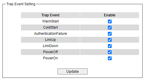
Spanning Tree
IEEE 802.1D Standard spanning tree functionality is supported by Welotec’s managed switches. The Spanning Tree Protocol (STP) provides a function to prevent switching loops and broadcast radiation at the OSI layer 2. A switching loop occurs in a network when there are multiple connections or redundant paths between two network switches or at least two ports are connected on both sides of the two network switches. The switching loop can create a broadcast radiation, which is the accumulation of broadcast and multicast traffics in a computer network. As broadcast and multicast messages are forwarded by bridges/switches to every port, the bridges/switches will repeatedly rebroadcast the broadcast messages, and this accumulation of traffic can flood the network. STP creates a spanning tree topology and disables those links of the network that are not part of the spanning tree, which leaves only a single active path between two nodes. This function can avoid flooding and increase network efficiency. Therefore, Welotec’s managed switches deploy spanning tree as a tool when the users set up connection or port redundancy or fault-tolerance in their network.
RSTP (RapidSpanning Tree Protocol), IEEE 802.1W then superseded by IEEE 802.1D-2004, is also supported in Welotec’s managed switches. It is an evolution of the STP, but it is still backwards compatible with standard STP.
RSTP has the advantage over the STP. When there is a topology change such as link failure in the network, the RSTP will converge significantly faster to a new spanning tree topology. RSTP improves convergence on point-to point links by reducing the Max-Age time to 3 times Hello interval, removing the STP listening state, and exchanging a handshake between two switches to quickly transition the port to forwarding state.
MSTP (Multiple Spanning TreeProtocol) is also a standard defined by the IEEE 802.1s that allows multiple VLANs to be mapped to a single spanning tree instance called MST Instance, which will provide multiple pathways across the network. It is compatible with STP and RSTP. To support lager network, MSTP groups bridges/switches into regions that appear as a single bridge to other devices. Within each region, there can be multiple MST instances. MSTP shares common parameters as RSTP such as port path costs. MSTP also help prevent switching loop and has rapid convergence when there is a topology change. It is possible to have different forwarding paths for different MST instances. This enables load balancing of network traffic across redundant links.
This section describes how to setup the spanning tree protocol (STP), rapid spanning tree protocol (RSTP), and Multiple Spanning Tree Protocol (MSTP). Figure 2.119 depicts the dropdown menu for Spanning Tree.
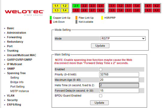
Spanning Tree Setting
The users can select the spanning tree mode which are based on different spanning tree protocols in this webpage. Figure 2.120 shows the mode setting for spanning tree. There are three spanning tree modes to choose from the dropdown menu, which are spanning tree protocol (STP), rapid spanning tree protocol (RSTP), and multiple spanning tree protocol (MSTP). After choosing the desired mode, please click Update button to allow the change to take effect.
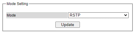
Under the mode setting, there is a box for Main Setting of spanning tree’s parameters as showed in Figure 2.121. The users can enable or disable spanning tree protocol in the Main Setting by checking the box behind the Enabled option. The users can fine tune the Priority, Maximum Age, Hello Time, and Forward Delay. Additionally, the BPDU Guard option can also be enabled by checking the box behind the BPDU Guard Enabled. Note that the Bridge Protocol Data Unit (BPDU) guard feature can be enabled to protect spanning tree protocol (STP) topology from BPDU related attacks. After configuring the spanning tree’s main parameters, please click Update button to allow the change to take effect. The description of each parameter is listed in Table 2.37.
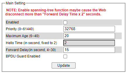
When the users change the spanning tree mode setting to MSTP and click the Update button in the Mode Setting box Figure 2.120, the Main Setting box in Figure 2.121 will be changed to Figure 2.122. The user can notice that the Priority field is disappeared while there are three more fields show up which are Max Hops, Revision Level, and Region Name. Additionally, there will be a note add to the Per-port Setting box that currently MSTP mode does not support trunk port now.
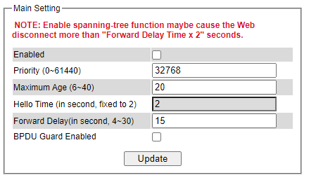
Table 2.37 Descriptions of Spanning Tree Parameters:
Label |
Description |
Default Factory |
|---|---|---|
Enabled |
Check the box to enable spanning tree functionality. |
Disable |
Priority |
Enter a number to set the device priority. The value is in between 0 and 61440. The lower number gives higher priority. |
32768 |
Maximum Age |
Maximum expected arrival time for a hello message. It should be longer than Hello Time. |
20 |
Hello Time |
Hello time interval is given in seconds. The value is in between 1 to10. |
2 |
Forward Delay |
Specify the time spent in the listening and learning states in seconds. The value is in between 4 to 30. |
15 |
Max Hops (Only for MSTP) |
The value is between 1 to 255. |
120 |
Revision Level (Only for MSTP) |
The value is between 0 to 65535. |
0 |
Region Name (Only for MSTP) |
Text string indicate the region name |
Region1 |
BPDU Guard Enabled |
Check the box to enable BPDU (Bridge Protocol Data Unit) guard |
Disable |
The bottom part of the Spanning Tree Setting is the Per-port setting as shown in Figure 2.123. The users can enable spanning tree functionality individually on each port or on all port by checking on the box under the Port Enable column. The default setting is checking on all port. After making any change on the per-port setting, please click on the Update button to update the change on the managed switch.
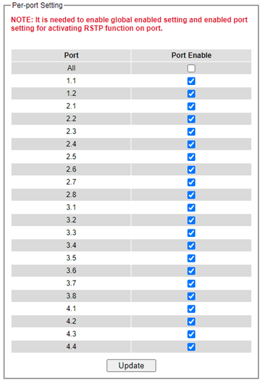
Bridge Info
Bridge Info (information) provides the statistical value of spanning tree protocol as shown in Figure 2.124. The information is further divided into two parts: Root Information and Topology Information. To check the latest information, please click on the Refresh button. Table 2.38 and Table 2.39 summarize the descriptions of each entry in the root information table and topology information table, respectively.
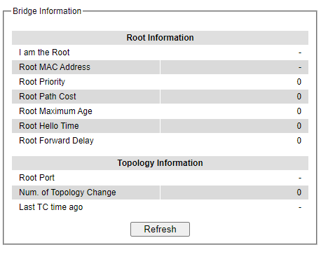
Table 2.38 Bridge Root Information:
Label |
Description |
Factory Default |
|---|---|---|
I am the Root |
Indicator that this switch is elected as the root switch of the spanning tree topology |
- |
Root MAC Address |
MAC address of the root of the spanning tree |
- |
Root Priority |
Root’s priority value :The switch with highest priority has the lowest priority value and it will be elected as the root of the spanning tree. |
0 |
Root Path Cost |
Root’s path cost is calculated from the switch’s port data rate. |
0 |
Root Maximum Age |
Root’s maximum age is the maximum amount of time that the switch will maintain protocol information received on a link. |
0 |
Root Hello Time |
Root’s hello time which is the time interval for RSTP to send out a hello message to the neighboring nodes to detect any change in the topology. |
0 |
Root Forward Delay |
Root’s forward delay is the duration that the switch will be in learning and listening states before a link begins forwarding. |
0 |
Table 2.39 Bridge Topology Information:
Label |
Description |
Factory Default |
|---|---|---|
Root Port |
A forwarding port that is the best port from non-root bridge/switch to root bridge/switch. Note that for a root switch there is no root port. |
- |
Num. of Topology Change |
The total number of spanning topology change over time. |
0 |
Last TC time ago |
The duration of time since last spanning topology change. |
- |
Port Setting
Spanning Tree Port Setting shows the configured value of spanning tree protocol for each port, as shown in Figure 2.125. The configured information for each port is state, role, path cost, path priority, link type, edge, cost, and designated information. To check the latest update on the statistics, please click on the Refresh button. Table 2.40 summarizes the descriptions of spanning three port setting. If Spanning Tree is enabled, the table below becomes editable. Use the Update button to save the settings.
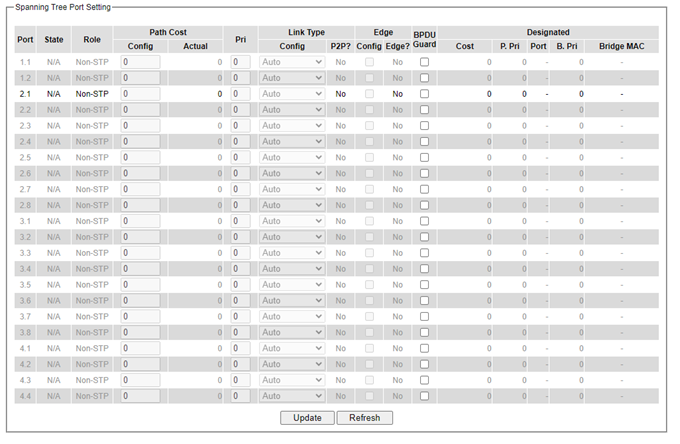
Table 2.40 Descriptions of Spanning Tree Port Setting
Label |
Description |
Factory Default |
|
|---|---|---|---|
Port |
The name of the switch port |
- |
|
State |
State of the port: ‘Disc’: Discarding - No user data is sent over the port. |
N/A |
|
Role |
Non-STP or STP RSTP bridge port roles: |
Non- STP |
|
Path Cost |
Setting the path cost for each switch port |
||
Config |
Setting path cost (default: 0, meaning that using the system default value (depending on link speed)) |
0 |
|
Actual |
The actual value path cost (For STP and RSTP, please see Note 1 below andTable 2.41.) |
0 |
|
Pri |
Setting the port priority, used in the Port ID field of BPDU packet, value = 16 × N, (N:0~15) See Note 2 below. |
128 |
|
Link Type |
The connection between two or more switches (for RSTP) |
||
Config |
Setting of the Link Type |
Auto |
|
P2P? |
Yes: This port is a Point-to-Point (P2P). |
No |
|
Edge |
Edge port is a port which no other STP/RSTP switch connect to (for RSTP). An edge port can be set to forwarding state directly. |
||
Config |
Edge functional is set: Yes or No |
No |
|
Edge? |
Yes: This port is an edge port. |
No |
|
PBDU guard |
To protect the layer 2 Spanning Tree Protocol (STP) Topology from BPDU related attacks |
No |
|
Designated |
This shows some information of the best BPDU packet through this port. |
||
Cost |
Root path cost |
0 |
|
P. Pri. (Port Priority) |
Port priority (high 4 bits of the Port ID), Value =16 × N, (N: 0~15) |
128 |
|
Port |
Interface number (lower 12 bits of the Port ID) |
- |
|
Bri. Pri. (Bridge Priority) |
Bridge priority, (value = 4096 × N, (N: 0~15) |
32768 |
|
Bridge MAC |
The MAC address of the switch which sent this BPDU |
- |
Note:
In general, the path cost is dependent on the link speed. Table 2.41 list the default values of path cost for STP and RSTP.
Table 2.41 Default Path Cost for STP and RSTP:
Data Rate |
STP Cost (802.1D-1998) |
RSTP Cost (802.1W-2004) |
|---|---|---|
4 Mbits/s |
250 |
5,000,000 |
10 Mbits/s |
100 |
2,000,000 |
16 Mbits/s |
62 |
1,250,000 |
100 Mbits/s |
19 |
200,000 |
1 Gbits/s |
4 |
20,000 |
2 Gbits/s |
3 |
10,000 |
10 Gbits/s |
2 |
2,000 |
The sequence of events to determine the best received BPDU (which is the best path to the root).
Lowest root bridge ID determines the root bridge.
Lowest cost to the root bridge favors the upstream switch with the least cost to root.
Lowest sender bridge ID serves as a tie breaker if multiple upstream switches have equal cost to root.
Lowest sender port ID serves as a tie breaker if a switch has multiple (non-Ether channel) links to a single upstream switch. Bridge ID = priority (4 bits) + locally assigned system ID extension (12 bits) + ID [MAC Address] 48 bits. The default bridge priority is 32768. Port ID = priority (4 bits) + ID (Interface number) (12 bits) The default port priority is 128.
MSTP Instance
MSTP enables the grouping and mapping of VLANs to different spanning tree instances. Therefore, an MST Instance (MSTI) is a particular set of VLANs that are all using the same spanning tree. Note that MSTI is identified by MSTI number and locally significant within MST region. Figure 2.126 illustrates the MSTP Instance webpage. In this section, the uses can add or remove MSTP instance. The upper part of the webpage is a table of existing MSTP instance in the managed switch. The users can add a new MSTP instance by choosing an Instance ID from the dropdown list, enter the VLAN Identification number in the VID field, and set the desired priority in the Priority field. After filling all information, please click the Add/Modify button to update the MSTP instance. The procedure for setting up an MSTP instance is as follows:
Enable MSTP protocol in Section 2.12.1
Modify spanning tree main setting as described in Section 2.12.1
Select ports that you want to enable MSTP function in Section 2.12.1.
Add a Multiple Spanning Tree Instance (MSTI) in MSTP Instance webpage (this section).
Choose an Instance Identification
Add VLAN Identification numbers (VIDs) that will be member(s)of MSTP instance.
Set Priority value of the switch.
Click Add/Modify button.
Table 2.42 summarizes the descriptions of MSTP Information.
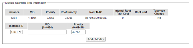
Table 2.42 Description of MSTP Information:
Label |
Description |
Factory Default |
|---|---|---|
Instance ID |
Choose from dropdown list of CIST (Common and Internal Spanning Tree) or choose value from 1 to 63 |
CIST |
VID |
Enter a value for VLAN ID between 1 to 4094 |
- |
Priority |
Enter a value for priority value for the managed switch between 0 – 61440. The lower value means the higher priority. If the priority value is 0, the switch will be the Root Bridge in this MSTI. |
32768 |
Root Priority |
Display root priority value |
32768 |
Root MAC |
Display MAC address of the Root Bridge |
- |
Internal Root Path Cost |
Display internal root path cost |
0 |
Root Port |
Display root port |
- |
Topology Change |
Display Yes or No |
No |
VLAN
A Virtual Local Area Network (VLAN) is a group of devices that can be located anywhere on a network, but all devices in the group are logically connected. In other words, VLAN allows end stations to be grouped together even if they are not located on the same network switch. With a traditional network, users usually spend a lot of time on devices relocations, but a VLAN reconfiguration can be performed entirely through software. Also, VLAN provides extra security because devices within a VLAN group can only communicate with other devices in the same group. For the same reason, VLAN can help to control network traffic. Traditional network broadcasts data to all devices, no matter whether they need it or not. By allowing a member to receive data only from other members in the same VLAN group, VLAN avoids broadcasting and increases traffic efficiency (see Figure 2.127).
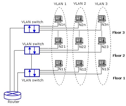
Welotec’s managed switch EHG75XX series provide six approaches to create VLAN as follows:
Tagging-based (802.1Q) VLAN
Port-based VLAN
MAC-based VLAN
IP Subnet-Based VLAN
Protocol-Based VLAN
QinQ or Double Tagging-based VLAN
Figure 2.128 shows the drop-down menu under the VLAN section.
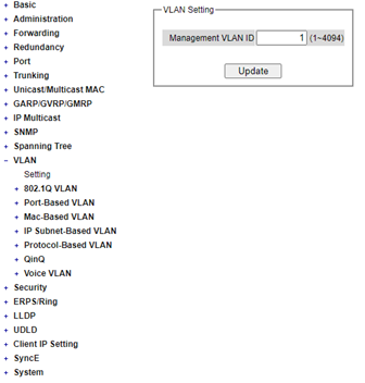
VLAN Setting
The first menu under the VLAN section is the VLAN Setting. Here the management VLAN Identification number (ID) is configured based on the IEEE 802.1Q standard. The default value is VID = 1. Note that the ID can be the number from 1 to 4096. If the users change the management VLAN ID to other number, please click the Update button to set it on the managed switch. Figure 2.129 depicts the VLAN Setting webpage. Table 2.43 describes the VLAN Setting option.
Table 2.43 Description of VLAN Setting:
Label |
Description |
FactoryDefault |
|---|---|---|
Management VLAN ID |
Configure the management VLAN ID that can be accessed this switch. Range from 1 to 4095. |
1 |
802.1Q VLAN
Tagging-based (802.1Q) VLAN is the networking standard that supports virtual LAN (VLANs) on an Ethernet network. The standard defines a system of VLAN tagging for Ethernet frames and the accompanying procedures for bridges and switches in handling such frames. The standard also contains provisions for a quality-of-service prioritization scheme commonly known as IEEE 802.1Q.
VLAN tagging frames are frames with 802.1Q (VLAN) tags that specify a valid VLAN identifier (VID). Whereas untagged frames are frames without tags or frames that carry 802.1p (prioritization) tags and only having prioritization information and a VID of 0. When a switch receives a tagged frame, it extracts the VID and forwards the frame to other ports in the same VLAN.
For an 802.1Q VLAN packet, it adds a tag (32-bit field) to the original packet. The tag is between the source MAC address and the EtherType/length fields of the original frame. For the tag, the first 16 bits is the Tag protocol identifier (TPID) field which set to a value of 0x8100 to identify the frame as an IEEE 802.1Q-tagged frame. This field is located at the same position as the EtherType/length field in untagged frames and is thus used to distinguish the frame from untagged frames. The next 3 bits is the Tag control information (TCI) field which refers to the IEEE 802.1p class of service and maps to the frame priority level. The next one bit is the Drop Eligible Indicator (DEI) field which may be used separately or in conjunction with PCP to indicate frames eligible to be dropped in the presence of congestion. The last 12 bits is the VLAN identifier (VID) field specifying the VLAN to which the frame belongs.
Under the 802.1Q VLAN menu, there are three submenus which are Setting, PVID Setting, and VLAN Table as shown in Figure 2.130.
802.1Q VLAN Settings
Figure 2.131 shows the 802.1Q VLAN Setting webpage which allow the users to add new tagged-based VLAN to the managed switch. Please follow the following procedure to setting up the 802.1Q VLAN on the switch.
Go to 802.1Q VLAN, then select Setting submenu.
Fill in appropriate Name, VID, Member Ports, and Tagged Ports as show in Figure 2.131. The description of each field is summarized in Table 2.44. Then, click Add/Modify button. Note to select multiple Member Ports or multiple Tagged Ports, press, and hold the Ctrl key while selecting multiple ports.
Go to 802.1Q VLAN’s PVID Setting described in the next subsection.
Choose the same ports and enter PVID (which is the same as VID), see Figure 2.132.
To remove any of the VLAN from the 802.1Q VLAN setting, click the Remove button at the end of that VLAN record as shown in Figure 2.131.
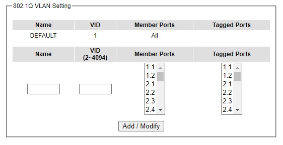
Table 2.44 Setting Descriptions of 802.1Q VLAN Settings:
Label |
Description |
Factory Default |
|---|---|---|
Name |
The VLAN ID name that can be assigned by the user. |
Factory Default |
VID |
Configure the VLAN ID that will be added in static VLAN table in the switch.The VLAN ID is in the range 2~4094. |
Dependent |
Member Ports |
Configure the port to this specific VID. |
All Ports |
Tagged Ports |
Configure the port that outgoing packet is tagged or untagged. Selected: The outgoing packet is tagged from this port. Unselected: The outgoing packet is untagged from this port. |
Dependent |
*NOTE: Default settings only have VLAN ID on 1. To set VLAN ID to other value beside 1, users will have to assign ports to be in that VLAN group.
802.1Q VLAN PVID Settings
Each port is assigned a native VLAN number called the Port VLAN ID (PVID). When an untagged frame goes through a port, the frame is assigned to the port’s PVID. That is the frame will be tagged with the configured VLAN ID defined in this subsection. Figure 2.132 shows the PVID Setting for 802.1Q VLAN where the upper table lists the current PVID assigned to each port. The users can configure the PVID by select either on or multiple ports (by clicking and holding the Ctrl key) and enter the desired PVID value between 2 to 4094. Please click Update button to allow the configuration to take effect on the switch. Table 2.45 summarizes the PVID Setting’s descriptions.
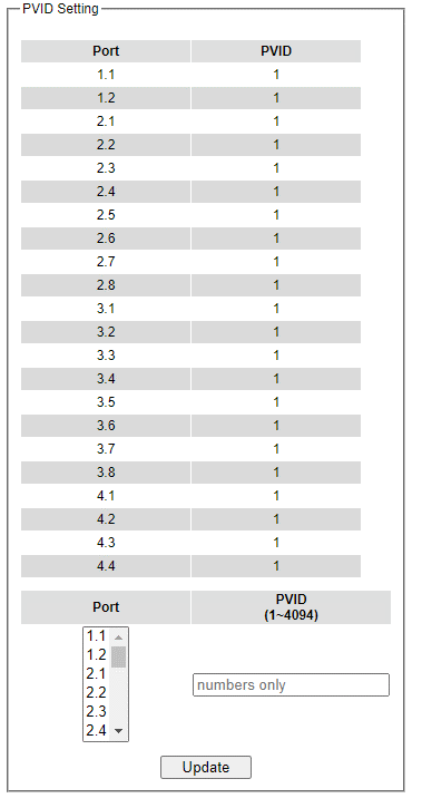
Table 2.45 Setting Descriptions of 802.1Q VLAN PVID:
Label |
Description |
Factory Default |
|---|---|---|
Port |
Select specific port(s) to set the PVID value |
- |
PVID |
Configure the default 802.1Q VID tag assigned to specific Port. The VLAN ID is in the range 1~4094. |
1 |
802.1Q VLAN Table
This webpage shown in Figure 2.133 displays the 802.1Q VLAN table which lists all the VLANs that are automatically and manually added/modified to the managed switch. Figure 2.134 illustrates examples of the static and dynamic VLAN information of each VID. Table 2.46 summarizes the descriptions of VLAN Table.
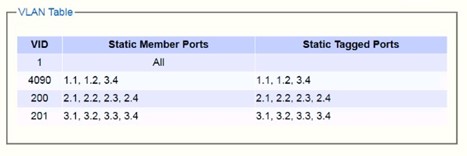
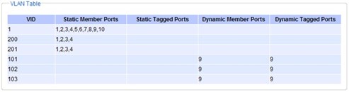
Table 2.46 Descriptions of 802.1Q VLAN Table:
Label |
Description |
Factory Default |
|---|---|---|
VID |
Indicate the VLAN ID number |
Dependent |
Static Member Ports |
Indicate the member ports to this VID. This entry is created by user. |
All ports |
Static Tagged Ports |
Indicate the ports that outgoing packet is tagged or untagged. Displayed: The outgoing packet is tagged from this port. Non-displayed: The outgoing packet is untagged from this port. This entry is created by user. |
Dependent |
Dynamic Member Ports |
Indicate the member ports to this VID. This entry is created by GVRP (discussed in Section 2.9.3). |
Dependent |
Dynamic Tagged Ports |
Indicate the member ports whose outgoing packet is tagged. Displayed: The outgoing packet is tagged from this port. Non-displayed: The outgoing packet is untagged from this port. This entry is created by GVRP (discussed in Section 2.9.3). |
Dependent |
Port-Based VLAN
Port-Based VLAN (or Static VLAN equivalent) assignments are created by assigning ports to a VLAN. If a device is connected to a certain port, the device will be assigned a VLAN to that specific port. If a user changes the connected port, a new port-VLAN assignment must be reconfigured for this new connection. To setup port based VLAN, please follow the following steps:
Click on Port-Based VLAN setting page as shown in Figure 2.135.
Select specific ports to be included in certain group by checking the corresponding box under the Member ports on row of port-based VLANs’ Group ID. Note that if the users check the box under the Group ID column, all the Member Ports will belong to that VLAN’s Group ID.
Click on the Update button to allow the setting to take effect on the managed switch.
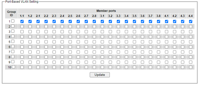
MAC-Based VLAN
The managed switch also supports the ability to assign a VLAN ID (VID) to an untagged packet based on the source MAC address. This can be set in this sub-menu as shown in Figure 2.135. There is maximum 512 entries in the MAC-based VLAN table (Source MAC address + VLAN ID) in the lower part of this webpage. If the users enter a duplicated MAC address into the MAC-based VLAN table, the old VLAN ID will be overwritten by the new VLAN ID. The VLAN ID range is between 1 to 4096. If the source MAC address of a packet is matched with any entry inside the MAC-based VLAN table here, the mapped VLAN ID will be added to the packet.

IP Subnet-Based VLAN
This sub-menu allows the user to assign a VLAN ID to an untagged packet based on the source IP address and the prefix length which is called IP subnet based VLAN. Figure 2.137 shows the webpage where the users can enter the IP address, prefix length and VLAN ID (VID) for creating a VLAN based on its IP subnet. The list of existing IPs subnet based VLAN is shown in the lower part of the webpage. This feature support maximum of 64 sets (IP address + Prefix length + VLAN ID). The VLAN ID (VID) range is between 1 to 4096. This VLAN setup feature supports both IPv4 and IPv6. If a duplicated pair of IP address and prefix length is entered into the table, there will be an error message. The prefix length of IPv4 is 0 to 32 while the prefix length of IPv6 is 0 to 64.
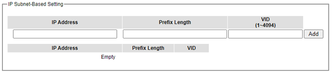
Protocol-Based VLAN
For the protocol based VLAN, the switch supports 3 Ethernet packet frame types: Ethernet II, 802.3 LLC, and 802.3 SNAP. It uses the EtherType field (Protocol ID) in these frames to assign a VLAN ID for each untagged packet. There are two submenus for Protocol-Based VLAN: Protocol to Group Setting and Group to VLAN Setting.
Protocol to Group Settings
The users can add or modify the Group ID in this menu option, as shown in Figure 2.138. Here, the maximum of 16 rules are supported. “Protocol Group Setting” is used to define the protocol rule and assign a unique ID (Group ID). The value of Group ID is between 1 to 2147483646. The Frame Type can be Ethernet, SNAP, or LLC. The “Value” field in the webpage is the EtherType (Protocol ID).
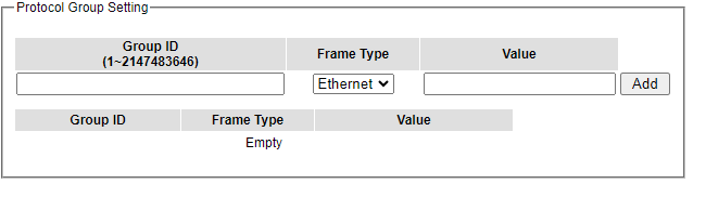
Group to VLAN Settings
The users can add or modify Group ID and for each port or multiple ports in this menu option, as shown in Figure 2.139. “Group to VLAN Setting” is used to map the Group ID to a VLAN ID (VID). This will map the FrameType and EtherType to a VLAN ID.

QinQ
Originally the 802.1Q standard VLAN only allowed one VLAN tag appended in a packet. But the QinQ feature in this subsection allows two VLAN tags to be appended in a packet. The main purpose of the QinQ is for service providers to place additional VLAN tag as an external network identification and to keep the original customer’s VLAN tag if existed.
To understand the operation of QinQ VLAN setting, we will use an example of a network where there are two buildings called Building 1 and Building 2 that has two departments called Department A and Department B of the same company on both buildings. Department A want to use the VLAN2 (TPID = 0x8100) for inside communication and Department B also want to use the VLAN2 (TPID = 0x8100) for inside communication, but they do not want to communicate with each other.
The network administrators can enable the QinQ VLAN feature or double tagging VLAN function in the company managed switches. If Building 1 has the following switches: A1 (for Department A), B1 (for Department B), H1 (for Backbone network) and Building 2 has the following switches: A2 (for Department A), B2 (for Department B), and H2 (for Backbone network) then all of the switches can be configured as shown in Figure 2.140.
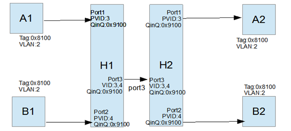
The operation of the network in Figure 2.140 based on QinQ VLAN setting rule can be described as follows.
Switch A1 and Switch B1 send some packets with VLAN tag (TPID=0x8100, VLAN ID=2) to H1.
The Switch H1 treats these received packets with VLAN tag (TPID=0x8100) as untagged packets because the receiving ports’ QinQ TPID = 0x9100. These packets will be inserted the second VLAN tags (TPID=0x9100, VLAN ID = PVID).
The Switch H1 will switch these packets to Port3 (VLAN ID=3 or 4 depending on the incoming port number from A1 or B1).
The Switch H2 receives these packets and switches them by the VLAN rule. The packets with VLAN ID 3 will be sent to Port 1 and the packets with VLAN ID 4 will be sent to Port 2.
Before Switch H2 sends these packets out from Port 1 or Port 2, the VLAN tags (TPID=0x9100, VLAN ID=3 or 4) will be removed from these packets.
Figure 2.141 shows the QinQ Setting webpage where the QinQ function can be enabled for each port on the managed switch. When checking the corresponding enabled box behind each port, the TPID field will become active. The default TPID is set to 0x8100 which means that the QinQ feature is disable. To enable the QinQ for a port, the users need to set the TPID value. In general, it should be set to 0x9100 which must be different from the original tag’s 0x8100 as described in Section 2.13.2. The TPID value should be between 0x0000 to 0xFFFF. When setting a trunk port with QinQ, it does not allow each physical port with different QinQ setting. This means that the QinQ enabled fields and TPID fields of all physical ports in a trunk port must be the same.
The QinQ setting rule is summarized as follows:
For ingress ports and egress ports, they use the TPID field to decide whether a packet is being with a VLAN tag or not.
A packet is untagged (without VLAN tag) if its TPID field is not the same as the TPID that we set for the port in the QinQ configuration.
A packet is tagged (with VLAN tag) if its TPID field is the same as the TPID that we set for the port in the QinQ configuration.
Either tagged packet or untagged packet are processed by the general VLAN rule to tag a packet, untag a packet, or keep the same packet, and do the switching.
When a packet is tagged with a VLAN tag. The tag’s TPID is from the input port’s QinQ setting and the tag’s VLAN ID is from the input port’s PVID setting.
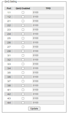
After finish setting the QinQ feature for any of the port, please click the Update button to allow the setting take effect on the managed switch.
Voice VLAN
A voice VLAN is a VLAN (virtual local area network) that is specifically allocated for user’s voice data streams. It can control the transmission priority of the passing voice traffic and other traffic when transmitted with other traffic. When other services (data, video, etc.) are transmitted simultaneously, the voice service can be set as high priority transmission or low priority transmission to ensure that the voice service can be transmitted with a higher forwarding priority or other services can be transmitted with a higher priority.
Voice VLAN Settings
The users need to refer “2.13.8.2 802.1Q VLAN Settings” to create one vlan, then add ports to vlan and untagged for voice vlan. Then the users can configure the Voice VLAN setting in this menu option, as shown in Figure 2.138.
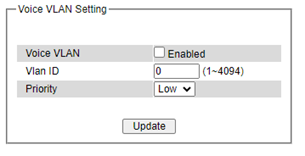
Voice VLAN State: Select to enable or disable Voice VLAN. The default is Disabled. Before you enabled Voice VLAN, you must configure the Voice VLAN Global Settings.
VLAN ID: The ID of VLAN that you want to assign voice traffic to. You must first create a VLAN from the 802.1Q VLAN page before you can assign a dedicated Voice VLAN. The member port you configured in 802.1Q VLAN setting page will be the static member port of voice VLAN. To dynamically add ports into the voice VLAN, please enable the Auto Detection function.
Priority: The 802.1p priority levels of the traffic in the Voice VLAN. Default Priority is set to LOW.
Aging Time: Enter a period (in hours) to remove a port from the voice VLAN if the port is an automatic VLAN member. When the last voice device stops sending traffic and the MAC address of this voice device is aged out, the voice VLAN aging timer will start. The port will be removed from the voice VLAN after the expiration of the voice VLAN aging timer. Selectable range is from 1 to 120 hours.
From Port / To Port: A consecutive group of ports may be configured starting with the selected port.
Auto Detection: Switch will add ports to the voice VLAN automatically if it detects the device OUI matches the Telephony OUI configured in the Voice VLAN OUI Setting page. Use the drop-down menu to enable or disable the OUI auto detection function. The default is Disabled.
Status: Shows status of port if IP Phone connected to ports status set to “Connected” otherwise “None”.
Voice VLAN OUI Settings
This window allows the user to configure the user-defined voice traffic’s OUI. An Organizationally Unique Identifier (OUI) is the first three bytes of the MAC address. This identifier uniquely identifies a vendor, manufacturer, or other organization.
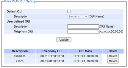
Default OUI: Pre-defined OUI values, including brand names of 3COM, Cisco, H3C, Pingtel, Siemens, NEC/Philips, Huawei3COM, and Avaya.
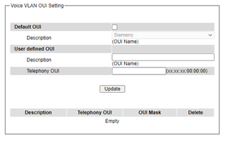
User defined OUI: You can manually create a Telephony OUI with a description.
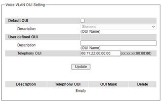
Security
Seven security features are provided in RSAGS series including the followings:
Port Security (Static)
802.1X
IP Source Guard
ARP Spoof Prevention
DHCP Snooping
Access Control List (ACL)
Dynamic ARP Inspection
Figure 2.146 shows the dropdown menu for security section on the managed switch.
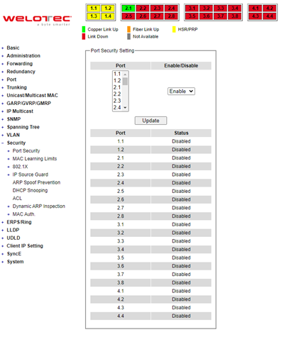
Port Security
Port Security or static port security subsection allows the users to control security on each port of the managed switch and create a table of MAC addresses allowed to access the switch. The Port Security menu is subdivided into two sub-menus which are Setting and White-List MAC.
Port Security Settings
Figure 2.147 displays the Port Security Setting webpage where the users can enable or disable static security on one or multiple ports. To enable or disable multiple ports at the same time please hold the Ctrl key and select multiple ports under the Port list and choose Enable or Disable and then click Update button. The lower part of the Port Security Setting webpage shows the status of security setting for each port on the managed switch.
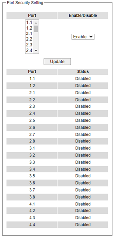
Port Security White-List MAC
The White-List MAC webpage is depicted in Figure 2.148. Users can create a list of MAC address that will be allowed to access the managed switch. Users will need to specify the VLAN ID (VID) and port number for each MAC address added to this list. After entering all required fields, please click on the Add button to add the new MAC address into the whitelist. Please remember that the same MAC address cannot be assigned to two different ports. This will cause an error message. Note that if there are existing MAC addresses on the list and the users would like to remove them, please click on the Remove button at the end of each record. Image below summarizes the descriptions of the fields in White-List MAC webpage.
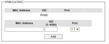
Table 2.47 Description of Fields in White-List MAC Webpage
Label |
Description |
|---|---|
MAC Address |
Type the suitable MAC address |
Ports |
Choose the desired ports |
Remove |
Option to remove the corresponding MAC address |
Add |
Click to add a MAC address |
VLAN |
Specify the corresponding VLAN address to MAC address. |
MAC Learning Limits
MAC limiting protects against flooding of the Ethernet switching table (also known as the MAC forwarding table or Layer 2 forwarding table). You enable this feature on interfaces (ports). MAC limiting sets a limit on the number of MAC addresses that can be learned dynamically on a single Layer 2 access interface or on all the Layer 2 access interfaces on the services gateway.
The managed switch support 3 source MAC addresses (first 3 MAC addresses) are learned on the specific port(s) and support user can clear the learned MAC addresses for re-learning the new MAC addresses on a specific port(s).
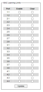
Table 2.48 Descriptions of MAC learning limitation:
Label |
Description |
|---|---|
Enable |
Enable/disable the MAC address learning limitation functionality on specific port(s) |
Clear |
To clear the learned MAC addresses for re-learning new MAC addresses on specific port(s) |
Update |
Update the settings |
802.1X
802.1X is an IEEE standard for port-based Network-Access Control. It provides an authentication mechanism to devices that want to attach to a LAN or WLAN. This protocol restricts unauthorized clients from connecting to a LAN through ports that are opened to the Internet. The authentication basically involves three parties (see Figure 2.150): a supplicant, an authenticator, and an authentication server.
Supplicant: A client device that requests access to the LAN.
Authentication Server: This server performs the actual authentication. We utilize RADIUS (Remote Authentication Dial-In User Service) as the authentication server.
Authenticator: The Authenticator is a network device (e.g.: the RSAGS Industrial Managed Switch) that acts as a proxy between the supplicant and the authentication server. It passes around information, verifies information with the server, and relays responses to the supplicant.
The authenticator acts like a security guard to a protected network. The supplicant is not allowed accessing to the protected side of the network through the authenticator until the supplicant’s identity has been validated and authorized. With 802.1X authentication, a supplicant, and an authenticator exchange EAP (Extensible Authentication Protocol, an authentication framework widely used by IEEE). Then the authenticator forwards this information to the authentication server for verification. If the authentication server confirms the request, the supplicant (client device) will be allowed to access resources located on the protected side of the network. RADIUS: The RADIUS is a networking protocol that provides authentication, authorization, and accounting (AAA) management for devices to connect and use a network service. Figure 2.150 shows a diagram of RADIUS authentication sequence.
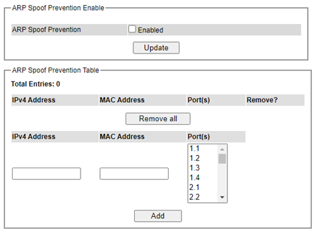
The 802.1X option under the Security section is subdivided into three sub-menus which are: Setting, Parameters Setting, and Port Setting.
802.1X Settings
The 802.1X security mechanism can be enabled in this webpage as shown in Figure 2.151. When the users check the Enabled box, the rest of the option fields will become active. The users then have to enter all the required fields to configure the 802.1X Setting which are the IP address of RADIUS server, the RADIUS server’s port number, RADIUS server’s accounting port number, NAS identifier, shared key and confirmed shared key. Additionally, the Forward 802.1x option can also be enabled in the last field. Summary of 802.1X Setting options are given in Table 2.49. After changing all the required fields, please click on the Update button.
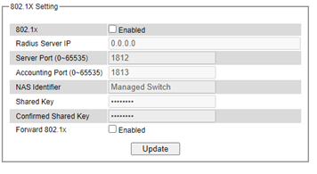
Table 2.49 Descriptions of 802.1X Setting:
Label |
Description |
Factory Default |
|---|---|---|
802.1x |
Choose whether to enable 802.1X for all ports or not |
Disabled |
Radius Server IP |
Set RADIUS server IP address |
0.0.0.0 |
Server Port |
Set RADIUS server port number. The range is 0 ~ 65535. |
1812 |
Accounting Port |
Set the accounting port number of the RADIUS server. The range is 0 ~ 65535. |
1813 |
NAS Identifier |
Specify the identifier string for 802.1X Network Access Server (NAS). Max. of 30 characters. |
Managed Switch |
Shared Key |
A shared key between the managed switch and the RADIUS Server. Both ends must be configured to use the same key. Max. of 30 characters. |
NULL |
ConfirmShared Key |
Re-type the shared key string. |
Dependent |
Forward 802.1x |
Choose whether to enable forwarding of 802.1x |
Disable |
802.1X Parameters Settings
There are several 802.1X parameters that the users might want to fine tune. This can be done on this webpage as shown in Figure 2.152. These parameters are related to the authentication periods or timeout durations and maximum number of authentication requests. Table 2.50 summarizes the descriptions of these parameters and their default setting. Please clicking on the Update button after the users changed any of the parameters.
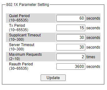
Table 2.50 Descriptions of 802.1X Parameters:
Label |
Description |
Factory Default |
|---|---|---|
Quiet Period |
Waiting time between requests when the authorization has failed. Range from 10 to 65535 seconds. |
60 |
Tx Period |
Waiting time for the supplicant’s EAP response packet before retransmitting another EAP request packet. Range from 10 to 65535 seconds. |
15 |
Supplicant Timeout |
Waiting time for the supplicant to response to the authentication server’s EAP packet. Range from 10 to 300 seconds. |
30 |
Server Timeout |
Waiting time for the authentication server to response to the supplicant’s EAP packet. Range from 10 to 300 seconds. |
30 |
Maximum Requests |
Maximum number of the retransmissionsthat the authentication serversends EAP request to the supplicant before the authentication session times out. Range from 2 to 10 seconds. |
2 |
Reauth Period |
Time between periodic re-authentication of the supplicant. Range from 30 to 65535 seconds. |
3600 |
802.1x Port Setting
The user can individually configure 802.1x security mechanism on each port of the RSAGS managed switch as shown in Figure 2.153. Each port can be set for any of the four authorization modes which are Force Authorization, Force Unauthorization, IEEE 802.1X Standard Authorization, and no authorization (N/A) as described in Table 2.51. The lower part of the webpage is a table display the status of authorization mode and state of each port on the managed switch. To enable the 802.1X security on any of the port(s), click one of the port or press Ctrl key and click multiple ports on the list and choose the Authorization Mode from the pulldown list and click the Update button. To check the latest status of the 802.1X port setting, please click on the Refresh button.
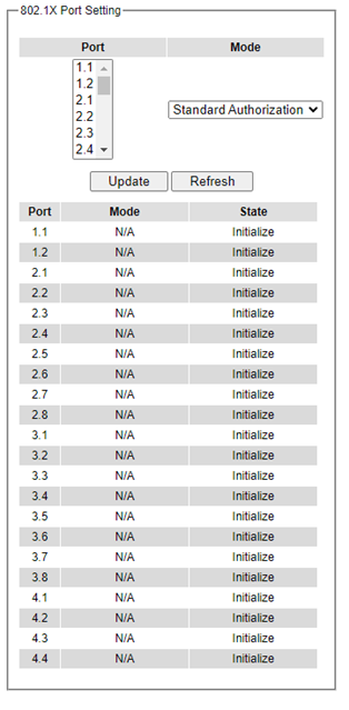
Table 2.51 Descriptions of 802.1X Port Setting:
Label |
Description |
Factory Default |
|
|---|---|---|---|
Port |
Set specific ports to be configured. |
Option |
|
Mode |
Choices: |
N/A |
IP Source Guard
IP Source Guard is another security feature in RSAGS managed switch that provides source IP address filtering on a Layer 2 port. This is to prevent a malicious host from impersonating a legitimate host by assuming the legitimate host’s IP address. This security feature uses dynamic DHCP snooping and static IP source binding to match IP addresses to hosts on untrusted Layer 2 access ports. Users can view two submenus: IP Verify Source and IP Source Binding where inside each of which has two submenus Setting and Status as show in Figure 2.154.
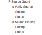
IP Verify Source Setting
The IP Verify Source is a dynamic IP Source Guard that creates a Layer-2 packet filtering on each port of the RSAGS. The filter types can be IP or IP-MAC. For IP filter type, RSAGS will check only the Source IP address of the packets. For IP-MAC filter type, RSAGS will consider both Source IP address and Source MAC address of the packets. Figure 2.155 shows the IP Verify Source Setting webpage. To enable IP verify Source filtering on a port, check the corresponding Enable box and choose a Filter-type from the dropdown list. After finish configuring, click on the Update button to active the filtering. After a filter was activated, all incoming packets to a configured port will be dropped. Only the packets that conform to specific Source and MAC addresses will be allowed to pass.
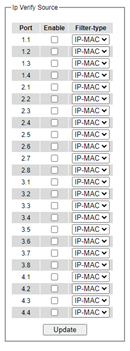
IP Verify Source Status
The user can check the status of IP Verify Source guard setting on each port in this webpage as shown in Figure 2.156. For each entry in the status table, there will be port number, Filter-type, Filter-mode, IP Address, and MAC Address. Note that if the DHCP snooping function was not enable or no traffic on the port, you will see the notification “inactive-no-snooping” message in each entry. To enable the DHCP snooping feature on the RSAGS, go to Section 2.14.6.
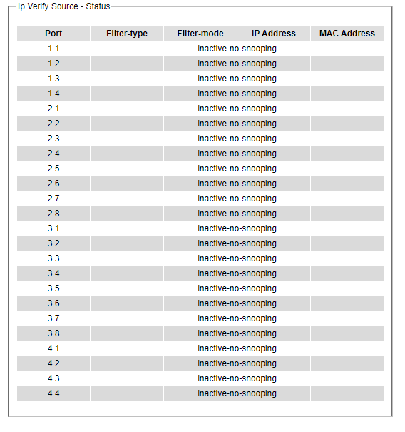
IP Source Binding Setting
The IP Source Binding is a static IP Source Guard that creates a Layer-2 packet filtering on each port of the RSAGS. This packet filter will require specific Source IP Address and Source MAC Address to be entered for each port. To enable IP Source Binding filtering on a port or multiple port, the user must enter the Source MAC Address and the Source IP Address in the corresponding textboxes as shown in Figure 2.157. Then, check the boxes for all required ports. Then, click Add button to add the filtering entry for IP Source Binding. An entry of IP Source Binding filtering will be listed in the table in the lower part of the webpage.
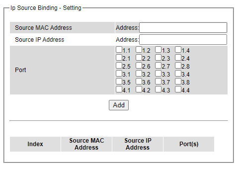
IP Source Binding Status
The user can check the status of IP Source Binding guard setting based on MAC Address and IP address pairs in this webpage as shown in Figure 2.158. For each entry in the status table, there will be MAC Address, IP Address, Lease (seconds), Type of Filtering, and list of Ports.
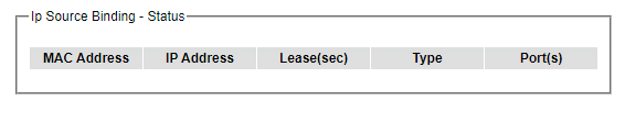
ARP Spoof Prevention
ARP (Address Resolution Protocol) Spoof Prevention is a security mechanism supported by Welotec’s RSAGS series to prevent ARP spoof attacks. The ARP spoof attack is a kind of network security attacks that a malicious host or node sends a falsify ARP messages over a local area network. This type of attack is also called ARP spoofing, ARP cache poisoning, or ARP poison routing. Typically, the attacker would like other hosts/nodes in the network to link or map the malicious Ethernet MAC address to a legitimate IP address of a victim host/node.
When ARP Spoof Prevention is enabled on RSAGS series, the ARP spoof prevention table must also be set with prevention entries. Each entry consists of IPv4 Address, MAC Address, and Port number(s). The IP Address and the MAC address in each entry belong to a legitimate or valid host/node that the administrator assigned or approved and the administrator of RSAGS want to protect that host/node from being spoofed. The port number can be one or group or all of the ports on RSAGS that will be accepting incoming ARP packets from the network. If there are incoming ARP packets to RSAGS and both IP address and MAC address of the ARP packets match one of the entries in the table, the ARP packets will be accepted by the RSAGS system. If the sender’s IP address of an ARP packet matches the IP address in one of the entries in the table but the sender’s MAC address of the ARP packet does not match, the RSAGS will drop the ARP packet on its port. Note that RSAGS will bypass or accept other ARP packets whose sender IP is not in the ARP Spoof Prevention Table.
DHCP Snooping
A rogue DHCP (Dynamic Host Control Protocol) server may be set up by an attacker in the network to provide falsify network configuration to a DHCP client such as wrong IP address, in-correct subnet mask, malicious gateway, and malicious DNS server. The purpose of DHCP spoofing attack may be to redirect the traffic of the DHCP client to a malicious domain and try to eavesdrop the traffic or simply try to prevent a successful network connection establishment. To protect against a network security attack of rogue DHCP server or DHCP spoofing attack, Welotec’s RSAGS provides DHCP Snooping feature. When this feature is enabled on specific port(s) of RSAGS managed switch, the RSAGS will allow the DHCP messages from trusted ports to pass through while it will discard or filter the DHCP messages from untrusted ports.
To enable the DHCP Snooping feature, check the Enabled box behind the DHCP Snooping option under the DHCP Snooping webpage as shown in Figure 2.160. By default, all interfaces of RSAGS are untrusted for DHCP Snooping. To configure specific port(s) as trusted port(s), simply check the box under the Trust column for that Port(s). Finally, click the Update button at the bottom of the webpage to activate the DHCP Snooping on the selected port(s). Note that the table inside the DHCP Data box will show information of the IP-to-MAC mapping, the Request Port and Lease Time of DHCP. To obtain the latest information on the bindings table, click on the Refresh button.
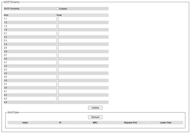
ACL
Access Control List (ACL) is the mechanism for network access control. The users configure the switch’s filtering rules for accepting or rejecting some packets. Two types of filters are deployed in the RSAGS series: 1) by MAC layer, and 2) by IP layer.
The numbers of matching rules can be at most 128. However, the main important rules that are mostly exercise are follows. Rules for filtering by MAC layer includes MAC address, VLAN ID or Ether type. Whereas rules for filtering by IP layer includes IP protocol, IP address, TCP/UDP port or Type of Service (TOS). When filtering is enabled, the matching rules are used to check whether the receiving packet is matched. If it is match, the packet will be rejected; otherwise, it will be accepted. Note here that the matching rules later will be referred to as the entries of ACL.
The ACL webpage is depicted in Figure 2.161. To differentiate between each ACL entry, Index number from 1 to 128 is used. The ACL entry that has higher priority will be checked first before the lower priority. The Name field is for setting name of this rule. Type of filtering whether MAC layer (“Mac Base”) and IP layer (“IP Base”) can be set in the Filter field. Note that when change from Mac Base to IP Base the required parameters for ACL setting will be changed accordingly.
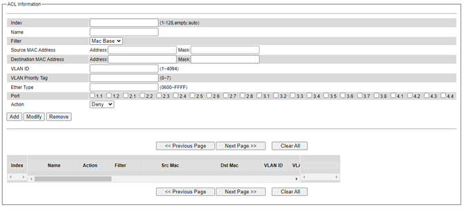
The main ACL entries for filtering by MAC layer (also called L2 filtering) as shown in Figure 2.161. Figure 2.161 include MAC address, VLAN ID, VLAN Priority Tag and Ether Type. Table 2.52 describes definition of each in details. Here note that if any field is empty, that ACL entry will be ignored.
Table 2.52 Description of Main ACL Entries for L2 Filtering in ACL Webpage:
ACL Entry |
Definition |
Range |
|---|---|---|
Source or Destination MAC Addresses |
MAC address are the fields of the Ethernet frame header. The Mask item is a bit mask for comparing range. |
For every non-zero bit in the Mask, its relative bit in the IP address will be compared. If the Mask is 0.0.0.0, then this condition is always accepted. If the Mask is empty, it is considered equal to the Mask of 255.255.255.255 and all of bits in the IP Address are compared. |
VLAN ID |
The VLAN ID field of 802.1Q VLAN tag in the Ethernet frame header. If the trunk ports are created, they will also be shown on the port list. If you want to select a trunk port, please make sure that there are no ACL entry using the physical ports which are belonging this trunk port. |
The item value is between 1~4094. |
VLAN Priority Tag |
The Priority field of 802.1Q VLAN tag in the Ethernet frame header. |
The item value is between 0~7. |
Ether Type |
The Ethernet type field in the Ethernet frame header. The followings are examples. The value 0x8000 is an IPv4 packet. The value 0x86DD is an IPv6 packet. The value 0x8100 is an 802.1Q packet. |
The item value is between 0~0xFFFF. |
The main ACL entries for filtering by IP layer (also called L3 filtering) as shown in Figure 2.162 include IP Protocol, Source IP Address, Destination IP address, TCP/UDP Source Port, TCP/UDP Destination Port and TOS. Table 2.53 describes definition of each in details. Once again, note that if any field is empty, that ACL entry will be ignored.
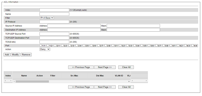
Table 2.53 Description of Main ACL Entries for L3 Filtering in ACL Webpage:
ACL Entry |
Definition |
Range |
|---|---|---|
IP Protocol |
The Protocol field of the IPv4 packet header. The followings are examples. The value 1 is for an ICMP packet. The value 6 is for the TCP packet. The value 17 is for the UDP packet. |
The item value is between 0~65535. |
Source or Destination IP Addresses |
The VLAN ID field of 802.1Q VLAN tag in the Ethernet frame header. The Mask item is a bit mask for comparing range. |
For every non-zero bits in the Mask, its relative bit in the IP address will be compared. If the Mask is 0.0.0.0.0.0, then this condition is always accepted. If the Mask is empty, it is considered equal to the Mask of FF:FF:FF:FF:FF:FF and all of bits in the IP Address are compared. |
TCP/UDP Source Port / TCP/UDP Destination Port |
The fields of TCP/UDP frame header. It is used to filter the application services. For example, the TCP Destination Port 21 is for the FTP service, the TCP Destination Port 23 is for the Telnet service and the TCP Destination Port 80 is for the HTTP service. To select which ports will follow the filter rule and what action to take, check the checkbox corresponding to that port and select choice of “Deny” or “Permit” in the action field. If this ACL entry is match, rejecting packet if ‘Deny’ is selected, and accepting packet if ‘Permit’ is selected. |
The item value is between 0~65535. |
TOS (Type of Service) |
A Differentiated Service Code Point (DSCP) field in an IPv4 header. It is used for providing Quality of Service (QoS). |
The item value is between 0~63. |
Table 2.54 Summary of Label, Description, and Factory Default for Both ACL Filtering Method:
LABEL |
DESCRIPTION |
FACTORY DEFAULT |
|---|---|---|
Index |
Priority (1-128) |
NONE |
Name |
Max length 32 |
NONE |
Filter |
Mac Base/IP Base |
Mac Base |
Source MAC Address and Mask |
A:B:C:D:E:F. is the MAC address. Mask is for bit mask checking. 0.0.0.0.0.0 is for accepting all. Empty is as FF:FF:FF:FF:FF:FF. |
NONE |
Destination MAC Address and Mask |
A:B:C:D:E:F. is the MAC address. Mask is for bit mask checking. 0.0.0.0.0.0 is for accepting all. Empty is as FF:FF:FF:FF:FF:FF. |
NONE |
VLAN ID |
1-4094 |
NONE |
VLAN Priority Tag |
0 ~ 7 |
NONE |
Ether Type |
0-FFFF |
NONE |
IP Protocol |
0-65535 |
NONE |
Source IP Address |
A.B.C.D is the IP address. Mask is for bit mask checking. 0.0.0.0 is for accepting all. Empty is as 255.255.255.255. |
NONE |
Destination IP Address |
A.B.C.D is the IP address. Mask is for bit mask checking. 0.0.0.0 is for accepting all. Empty is as 255.255.255.255. |
NONE |
TCP/UDP Source Port |
0-65535 |
NONE |
TCP/UDP Destination Port |
0-65535 |
NONE |
TOS |
0-63 |
NONE |
Port |
1,2,3,4,5,6,7,8, trk1, trk2 |
NONE |
Action |
Deny/Permit |
NONE |
The users can Add, Modify, or Remove each ACL entry based on the Index number as shown in Figure 2.161 and Figure 2.162. The lower part of the ACL Information webpage is the list of all ACL entries. The user can browse through the list by using the Previous Page and Next Page buttons. To remove all the ACL entries from the list, click on the Clear All button.
Dynamic ARP Inspection
Dynamic ARP Inspection (DAI) is another security feature provided by RSAGS managed switch to prevent a class of man-in-the-middle attacks. This type of attacks occurs when a malicious node intercepts packets intended for other nodes by poisoning the ARP caches of its unsuspecting neighbors. To create the attack, the malicious node sends ARP requests or responses mapping another node’s IP address to its own MAC address.
To prevent this kind of attack, RSAGS managed switch ensures that only valid ARP requests and responses are forwarded. Invalid and malicious ARP packets will be dropped by the switch. DAI relies mainly on DHCP snooping mechanism that listens to DHCP message exchanges. Then, DAI creates a bindings database of valid tuples of MAC address and IP address. DAI is related to the function of ARP Spoof Prevention described in Section 2.14.5. DAI will drop all ARP packets if the IP-to-MAC binding is not present in the DHCP snooping bindings database. However, if some static IP address is needed to pass through the switch, the user should add this static IP-to-MAC binding in the ARP Spoof Prevention webpage in Section 2.14.5. This static mapping is useful when nodes configure static IP address, DHCP snooping cannot be run, or other switches in the network do not run dynamic ARP inspection.
To enable DAI, check the Enabled box for DAI option inside the DAI with DHCP box as shown in Figure 2.163. Then, check the box under the Trust column for corresponding Port number to configure that port number as trusted port. Then click Update button. The table inside the DHCP Data box will show information of the IP-to-MAC mapping, the Request Port and Lease Time of DHCP. To obtain the latest information on the bindings table, click on the Refresh button. Note that if the DHCP Snooping was not enabled before enabling the dynamic ARP inspection with DHCP, the user will encounter the message shown in Figure 2.164.
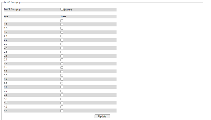
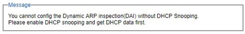
ERPS/Ring
Ethernet Ring Protection Switching (ERPS) is a protocol for Ethernet layer network rings. The protocol specifies the protection mechanism for sub-50ms delay time. The ring topology provides multipoint connectivity economically by reducing the number of links. ERPS provides highly reliable and stable protection in the ring topology, and it never forms loops, which can affect network operation and service availability.
In the Ethernet ring, loops can be avoided by guaranteeing that traffic may flow on all but one of the ring links at any time. This link is called Ring Protection Link (RPL). A control message called Ring Automatic Protection Switch (R-APS) coordinates the activities of switching on/off the RPL. Under normal conditions, this link is blocked by the Owner Node. Thus, loops can be avoided by this mechanism. In case an Ethernet ring failure occurs, one designated Ethernet Ring Node called the RPL Owner Node will be responsible for unblocking its end of the RPL to allow RPL to be used as a backup link. The RPL is the backup link when one link failure occurs. Welotec’s RSAGS series industrial managed switches provide several Ethernet ring protocols. The ERPS/Ring section is subdivided into six menus as shown in Figure 2.165, which are: ERPS Setting, iA-Ring Setting, C-Ring Setting, U-Ring Setting, Compatible-Chain Setting and MRP (Media Redundancy Protocol).
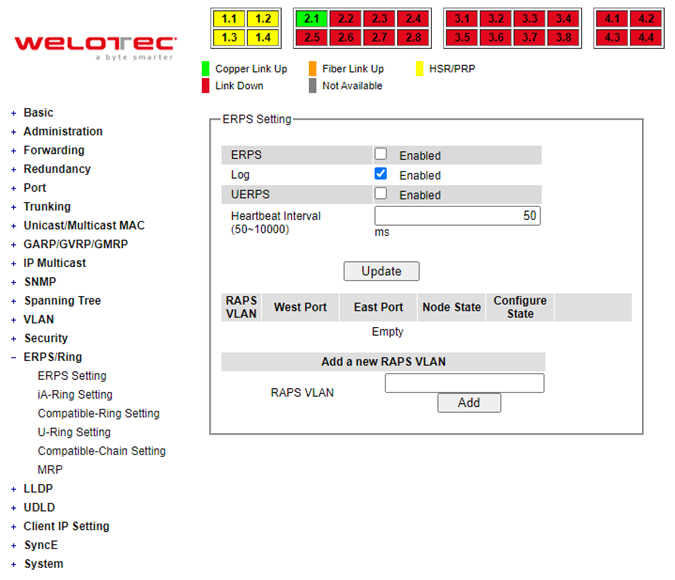
ERPS Setting
ERPS Setting webpage is shown in Figure 2.166. To set up ERPS on the current managed switch, please follow the following steps:
Enable the ERPS by checking on the ERPS’s Enabled checkbox.
If the users would like to keep the log, please also check the Log’s Enabled checkbox.
Optionally, if the users want the switch to periodically check the status of the neighboring switches on the ring topology using heartbeat packets, then the user can check the UERPS’s Enabled checkbox. Note that when this feature is enabled, the recovery time of the ring topology may be longer.
Optionally, the users can fine tune the heartbeat interval by changing the default value 50 milli-seconds to the desired value.
Click on the Update button.
Skip down to Add a new RAPS VLAN section at the bottom of the webpage. Enter the desired RAPS VLAN ID in the field and click the Add button. The VLAN ID can be the value from 1 to 4094. Table 2.55 summarizes the fields in ERPS Setting webpage.
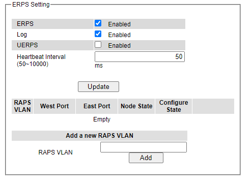
Table 2.55 Descriptions of ERPS Setting
Label |
Description |
Factory Default |
|---|---|---|
ERPS |
Choose whether to enable ERPS or not |
Disabled |
Log |
Choose to enable log |
Enabled |
UERPS |
Choose whether to enable UERPS. When UERPS is enabled, ring ports periodically sent a “heartbeat” packet to peer ring ports to determine whether the link path (etc. wireless bridge) is failure or alive. If peer ring port cannot receive “heartbeat” packets over 3 packets, the ring port will enter protection state. Note: This function affects the recovery time to more than 20 ms. |
Disabled |
Heartbeat Interval |
Set the Heartbeat Interval. Range from 50 to 10000 milliseconds. |
50 ms |
RAPS VLAN |
Create the ring by specifying the R-APS VLAN ID of the ring. VLAN ID ranges from 1 to 4094. |
NULL |
Click the Configure button on the right side of the webpage that corresponding to the RAPS VLAN that was entered in previous step. A new webpage will be displayed for the users to config additional parameters for ERPS RAPS VLAN Setting as shown in Figure 2.167.
Configure the RAPS VLAN’s Status, West Port, East Port, RPL Owner, RPL Port, WTR Timer, Holdoff Timer, Guard Timer, MEL, and Propagate TC. Detail description of these parameters are summarized in Table 2.56. Then, click Update button to finish the setting up of new RAPS VLAN.
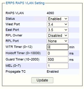
Table 2.56 Description of ERPS RAPS VLAN Setting:
Label |
Description |
Factory Default |
|---|---|---|
ERPS VLAN |
Indicate current RAPS VLAN ID to be configured |
None |
Status |
Choose to enable ERPS with this VLAN |
Disabled |
West Port |
Choose the West Port of the RPL |
None |
East Port |
Choose the East Port of the RPL |
None |
RPL Owner |
Choose to enable Owner Function |
Disabled |
RPL Port |
Select the Owner Port which is either West Port or East Port or None. |
None |
WTR Timer |
Set the wait-to-restore (WTR) time of the ring in minutes. Lower value has lower protection time. Range of the WTR Timer is from 0 to 12 minutes. |
5 |
Holdoff Timer |
Set the holdoff time of the ring. Range is from 0 to 10000 ms |
0 |
Guard Timer |
Set the guard time of the ring. Range is from 0 to 2000 ms |
500 |
MEL |
Set the maintenance entity group level (MEL)of the ring. Range is from 0 to 7 |
1 |
Propagate TC |
Indicate the topology change propagation of the ring ability. |
Enabled |
UERPS Setting (Optional)
The following procedure outlines the UERPS Setting under the ERPS Setting. You can follow them as an exercise.
Prepare two managed switches (Switch A and Switch B). We will use Port 7 and Port 8 on both switches for redundancy.
Connect Switch A and Switch B to the network or PC so that you can access them. For simplicity, the users can use Port 1 for Web configuration on both switches.
Open Device Management Utility and change the IP address of Switch B or both switches such that the IP addresses will not be conflicting.
Open Switch A and B’s Web UI and setup ERPS settings like the following. Enable ERPS, Log, and UERPS accordingly as shown in Figure 2.168. Then, press Update button for the changes to take effect.
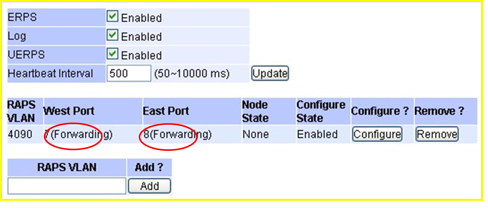
On Switch A, Click Configure button on RAPS VLAN and input settings as shown in Figure 2.169.
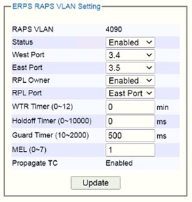
Open Switch B’s Web UI and input settings for ERPS.
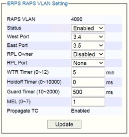
Connect Switch A’s Port 3.4 to Switch B’s Port 3.5 and connect Switch A’s Port 3.5 to Switch B’s Port 3.4 (like cross-over) for the redundancy port.
If everything is setup properly, you will find Switch A having the following ERPS state as shown in Figure 2.171. Also, it will automatically block Port 3.5 to prevent a network loop.
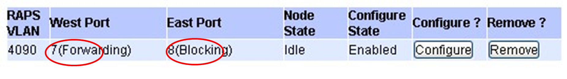
From here on, the users can add another bridge between the two managed switches.
iA-Ring Settings
The Welotec’s managed switch is designed to be compatible with iA-Ring protocol for providing better network reliability and faster recovery time for redundant ring topologies. It is in the same category as R Rings, but with its own protocol. It has been a successful development that reduces recovery time to less than 20 ms.
Figure 2.172 shows iA-Ring Setting webpage. The iA-Ring redundancy protocol can be enabled on this page. Note that the users should disable and disable ERPS as described in Section 2.15.1 first to enable/configure iA-Ring parameters on the web browser. Please follow the simple steps below based on Figure 2.172 to setup the iA-Ring.
Enable the iA-Ring by selecting Enabled from the dropdown list.
Choose whether the current managed switch is going to be the Ring Master by enabling the Ring Master option.
Select the 1st Ring Port from the dropdown list.
Select the 2nd Ring Port from the dropdown list.
Click on the Update button to save the change and allow the configuration to take effect.
Check the latest status of the iA-Ring configuration by clicking on the Refresh button.
Note that the lower part of the iA-Ring Setting webpage shows the Status of the iA-Ring which provides its State, 1st Ring Port Status and 2nd Ring Port Status. The description of the iA-Ring setting is summarized in Table 2.58.
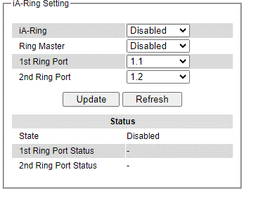
Table 2.58 Descriptions of iA-Ring Setting:
Label |
Description |
Factory Default |
|---|---|---|
iA-Ring |
Enable iA-Ring or disable iA-Ring. |
Disabled |
Ring Master |
Enabled: Master Mode. Disabled: Slave Mode. |
Disabled |
1st Ring Port |
Select the primary port for the iA-Ring. |
1.1 |
2nd Ring Port |
Select the backup port for the iA-Ring. |
1.2 |
C-Ring (Compatible-Ring) Settings
Compatible-Ring (C-Ring) is like iA-Ring. The only difference is that it can be used for MOXA rings as well. For more information about this redundant ring protocol, please contact Welotec.
Figure 2.173 shows how to set the Compatible-Ring (C-Ring) redundancy protocol. Note that the users should disable ERPS as described in Section 2.15.1 first to enable/configure Compatible-Ring parameters on the web browser. Please follow the simple steps below based on Figure 2.176 to setup the C-Ring.
Enable the C-Ring by selecting Enabled from the dropdown list.
Select the 1st Ring Port from the dropdown list.
Select the 2nd Ring Port from the dropdown list.
Click on the Update button to save the change and allow the configuration to take effect.
Note that the lower part of the C-Ring Setting webpage shows the Status of the C-Ring which provides its State, 1st Ring Port Status and 2nd Ring Port Status. The description of the C-Ring setting is summarized in Table 2.59.
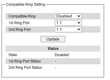
Table 2.59 Descriptions of Compatible-Ring Setting
Label |
Description |
Factory Default |
|---|---|---|
C-Ring (Compatible-Ring) |
Enables Compatible-Ring or disable Compatible-Ring. |
Disabled |
1st Ring Port |
Selects the primary port for the Ring. |
1.1 |
2nd Ring Port |
Selects the backup port for the Ring. |
1.1 |
U-Ring
This section enables the setup of U-Ring (Unicast Ring) on the managed switch. The U-Ring could provide redundancy connection between two RSAGS industrial managed switches which are not directly connected by physical wires but by two additional network devices on each switch. There are two examples of U-Ring application presented here to provide as guidelines when to choose this U-Ring feature.
On each switch it is connected to two wireless Access Points (AP) via two different Ethernet LAN ports. Both wireless Access Points are connected to another two wireless Access Points as two separate wireless bridge connection.
On each switch it is connected to two wired Access Points (AP) via two different Ethernet LAN ports. Both wired Access Points are connected to another two wired Access Points as two separate wired bridge connection. There are two physical lines between both pair of APs. The U-ring protocol could be used in this environment. The different of this example from the previous example is that the APx could be:
Unmanaged switch
Transceiver
XDSL bridge
Note that care should be taken that if a dumb switch is used as an AP (Access Point). The one on the other side must be a dumb switch as well. Again, care should also be taken when connecting the cables to the ports. To setup the U-Ring, the users need to configure several parameters on U-Ring Setting webpage as shown in Figure 2.174. Please follow the simple steps below to setup the U-Ring.
Enable the U-Ring by selecting Enabled from the dropdown list.
Choose whether the current managed switch is going to be the Ring Master by enabling the Ring Master option.
Select the 1st Ring Port from the dropdown list.
Select the 2nd Ring Port from the dropdown list.
Optionally, set the Heartbeat Expire period which could be between 100 to 10000 milliseconds. Note that the default period is 100 ms.
Click on the Update button to save the change and allow the configuration to take effect.
Check the latest status of the U-Ring configuration by clicking on the Refresh button.
Note that the lower part of the U-Ring Setting webpage shows the Status of the U-Ring which provides its State, 1st Ring Port Status and 2nd Ring Port Status. The description of the U-Ring setting is summarized in Table 2.60.
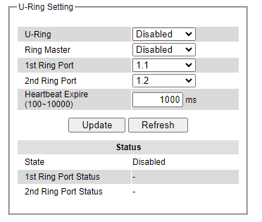
Table 2.60 Descriptions of U-Ring Setting:
Label |
Description |
Factory Default |
|---|---|---|
U-Ring |
Enabled or disabled the Unicast ring. |
Disabled |
Ring Master |
Enabled or disabled this switch as the Ring Master of the Unicast Ring. For Ring Slave configuration, leave this option as disabled. |
Disabled |
1st Ring Port |
Select which port on the managed switch will be the 1st Ring Port. |
1.1 |
2ndRing Port |
Select which port on the managed switch will be the 2nd Ring Port. |
1.2 |
Heartbeat Expire |
Time interval between checking-packets. |
1000 |
Update |
Click this button to allow the configuration to take effect. |
- |
Refresh |
Obtain the latest status of the U-Ring Setting by clicking on this button. |
- |
State |
Shows whether the device’s state is normal or protected. |
Disable |
1st Ring Port Status |
Displays the status of the 1st Ring Port. |
- |
2nd Ring Port Status |
Displays the status of the 2nd Ring Port. |
- |
Compatible-Chain Settings
The Compatible-Chain Setting is provided on Welotec’s managed switches for compatible networking with Moxa switch’s Turbo Chain. The MOXA’s Turbo Chain is a technique that uses the chain network topology and links the two ends (two network devices such as industrial managed switches) of the chain to a common LAN. This can also be viewed as a form of Ring Topology. This Turbo Chain can provide redundancy on any type of network topology or on complex network topology such as multi-ring architecture. The Turbo Chain can create flexible and scalable topologies with a fast media-recovery time.
The fist switch on the Compatible-Chain will have a Role State as Head switch. The other switches along the Compatible-Chain will have a Role State as Member switches. The last switch on the Compatible-Chain will have a Role State as Tail switch. For Head switch, the first port which is connected to the common LAN is called Head Port, while the second port which is connected to the next switch in the Compatible-Chain is called Member Port.
For Member switches, both ports of the Member switches are called 1st Member Port and 2nd Member Port. For Tail switch, the first port which is connected to another Member switch is call Member Port, while the second port which is connected to the common LAN is called Tail Port. In Turbo Chain configuration, the Head Port is the main path while the Tail Port is the backup path of the redundant topology. During no link-failure operation on the chain’s path, all traffic will be forwarded to the Head Port to the common LAN. When there is a failure on the path of the chain, the Tail Port will be used for forwarding the traffic to the common LAN.
To configure Compatible-Chain, select the Compatible-Chain menu under the ERPS/Ring Section. Figure 2.175 shows the Compatible-Chain Setting webpage.
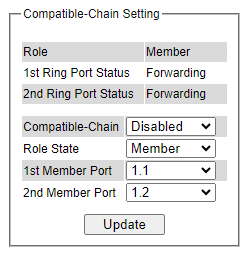
Please follow the simple steps below to setup the Compatible-Chain.
Enable the Compatible-Chain by selecting Enabled from the dropdown list.
Choose the Role State whether the current managed switch is going to be the Head, Member or Tail of the chain from the dropdown list of Role State.
If the current switch is the Head switch, then select the Head Port from the dropdown list and select the Member Port from another dropdown list.
If the current switch is the Member switch, then select the 1st Member Port from the dropdown list and select the 2ndMember Port from another dropdown list.
If the current switch is the Tail switch, then select the Tail Port from the dropdown list and select the Member Port from another dropdown list.
Click on the Update button to save the change and allow the configuration to take effect.
Note that the upper part of the Compatible-Chain Setting webpage shows the Status of the current switch in the chain which provides its Role, 1st Ring Port Status and 2nd Ring Port Status. The description of the Compatible Chain setting is summarized in Table 2.61.
Table 2.61 Descriptions of Compatible-Chain Setting:
Label |
Description |
Factory Default |
|---|---|---|
Role |
Display the role of the current switch in the Compatible-Chain: Head, Tail, or Member. |
Member |
1st Ring Port Status |
Display the status of the 1st Ring Port. |
Forwarding |
2nd Ring Port Status |
Display the status of the 2nd Ring Port. |
Forwarding |
Compatible-Chain |
Enabled or Disabled the Compatible-Chain Ring |
Disable |
Role State |
Choose the role of the current switch in the compatible chain: Head, Tail, or Member. |
Member |
Head Port |
Select a particular port from the dropdown list to be the Head Port of the compatible chain. |
1.1 |
Tail Port |
Select a particular port from the dropdown list to be the Tail Port of the compatible chain. |
1.1 |
Member Port |
Select a particular port from the dropdown list to be the Member Port of the compatible chain. |
1.2 |
1st Member Port |
Select a particular port from the dropdown list to be the Member Port of the compatible chain. |
1.1 |
2nd Member Port |
Select a particular port from the dropdown list to be the Member Port of the compatible chain. |
1.2 |
MRP
The Media Redundancy Protocol (MRP) is a data network protocol for Ethernet switch standardized by the International Electro technical Commission as IEC 62439-2. MRP is mostly used in and suitable for Industrial Ethernet applications. It allows rings of Ethernet switches to overcome any single failure with recovery time much faster than those achievable by Spanning Tree Protocol. It supports very fast failure recovery time. For example, a worst-case recovery time for 14 switches is about 10ms and for 50 switches is about 30ms.
The MRP includes following properties:
It operates at the MAC layer of the Ethernet switches.
It is a ring topology.
Any single failure can be recovered.
For switches in the network, there can be two roles:
Ring manager (MRM) o Ring client (MRC)
For ring ports, there are three possible statuses: disabled, blocked, and forwarding. o Disabled ring ports drop all the received frames.
Blocked ring ports drop all the received frames except the MRP control frames.
Forwarding ring ports forward all the received frames.
In normal case, one of the MRM ring ports is blocked to avoid looping and both ring ports of all MRCs are forwarding.
When a path of the ring fail, the other port on the MRM will become active and forwarding.
The Media Redundancy Protocol (MRP) menu under the ERPS Ring section enables an implementation of a redundant PROFINET communication through ring topology without the need for switches. Figure 2.181 shows the MRP Setting webpage. Please follow the outlined steps here to setup the MRP:
Enter a desired VLAN ID in the field at the bottom of the MRP Setting webpage and click Add button as shown in Figure 2.176.
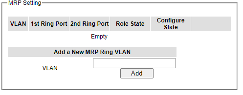
After the MRP Ring is created with the desired VLAN, there will be an entry of the MRP VLAN on the table at the top of the page as shown in Figure 2.177. There will also be two new buttons at the end of the entry: Configure and Remove. The users can click on the Configure button the continue setting up the MRP Ring on the managed switch.
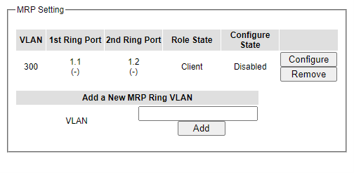
Table 2.62 Description of MRP Setting Webpage:
Label |
Description |
Factory Default |
|---|---|---|
VLAN |
MRP Ring VLAN ID |
Depend |
Role State |
Role status setting (Manager or Client) |
Client |
1st Ring Port |
Port number and port status (Link Down, Blocked, Forwarding). |
1.1 |
2ndRing Port |
Port number and port status (Link Down, Blocked, Forwarding). |
1.2 |
Configure State |
Enabled or Disabled state of MRP Ring function |
Disabled |
After clicking the Configure button on the desired entry, a new webpage called MRP Ring Setting will show up as shown in Figure 2.178.
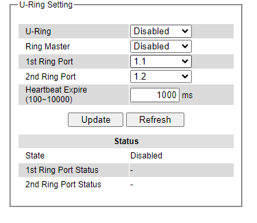
Then, the users can set MRP Ring parameters for the current switch, which are the Status, 1st Ring Port, 2nd Ring Port, and Rote State as described earlier. Table 2.63 summarizes the description of MRP Ring Setting parameters.
Click on the Update button to allow the configuration to take effect. Note that if there is other ERPS Ring Topology already setting up on the managed switch there may be an error message popping up as shown in Figure 2.179. Therefore, the users should disable the ERPS/Ring (Section2.15.1) first before setting up this MRP Ring.
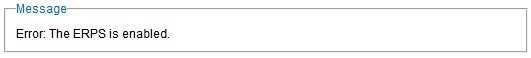
Table 2.63 Descriptions of MRP Ring Setting:
Label |
Description |
Factory Default |
|---|---|---|
Ring VLAN |
Display the current MRP Ring VLAN ID to be configured. |
Depend |
Status |
Disabled or Enabledthe ring function. |
Disabled |
1st Ring Port |
Select the 1st Ring Port from the dropdown list. |
1.1 |
2ndRing Port |
Select the2nd Ring port from the dropdown list. |
1.2 |
Role Status |
Select the role status to be either Ring Client or Ring Manager. |
Client |
LLDP
Link Layer Discovery Protocol (LLDP) is an IEEE802.1ab standard OSI layer-2 protocol. LLDP allows Ethernet network devices to advertise details about themselves, such as device configuration, capabilities, and identification. The advertise packets are periodically sent to directly connected devices on the network that are also using LLDP or so called its neighbors. LLDP is a “one hop” unidirectional protocol in an advertising mode.
LLDP information can only be sent to and received by devices, no solicit information or state changes between nodes. The device has a choice to turn on and off sending and receiving function independently. Advertised information is not forward on to other devices on the network. LLDP is designed to be managed with SNMP. Applications that use this protocol include topology discovery, inventory management, emergency services, VLAN assignment, and inline power supply.
Link Layer Discovery Protocol (LLDP) section consists of LLDP Setting and LLDP Neighbors as shown in Figure 2.180.

LLDP Settings
In Figure 2.181, the LLDP Setting webpage allows users to have options for enabling or disabling the LLDP, as well as setting LLDP transmission parameters. This LLDP function should be enabled if users want to use Welotec’s Device Management Utility (formerly called Device View) to monitor the switches ‘topology of all LLDP devices in the network. For more information about using Device Management Utility. Table 2.64 describes the LLDP Setting parameters which are transmit interval and transmit time-to-life of the LLDP advertisement packets.
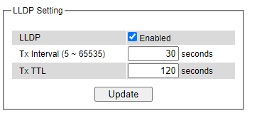
Table 2.64 Descriptions of LLDP Setting:
Label |
Description |
Factory Default |
|---|---|---|
LLDP |
Choose to either enable or disable LLDP. |
Enabled |
Tx Interval |
Set the transmit interval of LLDP messages. Range from 5 to 65535 seconds. |
30 |
TxTTL |
Tx Time-To-Live. Amount of time to keep neighbors’ information. The recommend TTL value is 4 times of Tx Interval. The information is only removed when the timer is expired. Range from 5 to 65535 seconds. |
120 |
LLDP Neighbors
This menu allows the user to view the LLDP’s neighbor information of the managed switch as shown in Figure 2.182. The Neighbor Information table contains Chassis ID, Port ID, Port Description, Device Name, Device Description and Management Address on each Port of the managed switch. The users can click on the Refresh button to get the latest Neighbor Information table or click on the Clear button to clear all the information on the display Neighbor Information table.
An example of neighbor information table is depicted in Figure 2.188. Note that this example is based on a display format of an early version of RSAGS managed switch in which System Name is changed to Device Name and System Description is changed to Device Description in the latest version of RSAGS’s firmware.
Table 2.65 summarizes the descriptions of each column of the LLDP’s Neighbor Information.
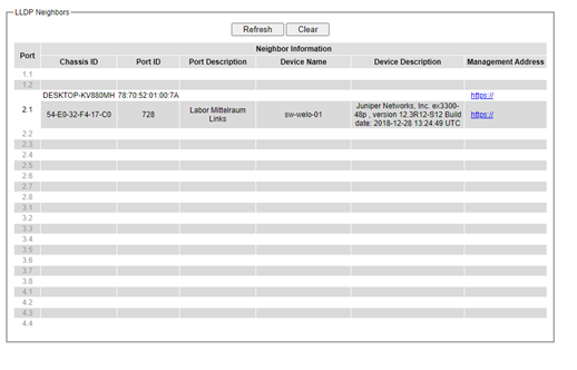
Table 2.65 Descriptions of LLDP Neighbors Webpage:
Label |
Description |
|---|---|
Port |
Indicates particular port number of the switch. |
Chassis ID |
Indicates the identity of the neighbor of this particular port. |
Port ID |
Indicates the port number of this neighbor. |
Port Description |
Shows a textual description of the neighbor port. |
Device Name |
Indicates the device name/ hostname of the neighbor. |
Device Description |
Shows a more detailed description of the neighbor’s device. |
Management Address |
Indicates neighbor’s management IP address. |
UDLD
The UniDirectional Link Detection (UDLD) protocol is a protocol that can be used to prevent Layer-2 switching loops in the network. The network loop problem usually occurs in Spanning Tree network topology (miswiring or malfunction of the network interface). UDLD is a data link layer (Layer-2) protocol that keeps track of physical layer configuration (fiber or copper). It helps detect switching loops and one-way connections. UDLD protocol requires that two neighboring switches UDLD packets to detect the unidirectional link. UDLD packets are transmitted periodically (hello interval) to its neighbor switches on LAN ports that has UDLD protocol enabled. If the UDLD packets are not echoed back within a specific time, the port will be shut down and flagged as unidirectional link. Welotec’s EHG75XX supports this protocol: the user can configure it under the UDLD menu as shown in Figure 2.183. Under the UDLD menu, there are three submenus: Setting, Port-info, and reset.
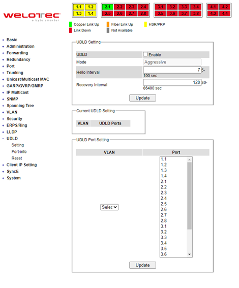
UDLD Setting
Enable UDLD protocol on EHG7XXX, the user needs to configure a UDLD VLAN. This can be done by selecting the setting submenu under the UDLD menu. The UDLD webpage is shown in Figure 2.184.
First the user must select a VLAN ID from a dropdown list and then select one or multiple ports from the list of the UDLD Port Setting part on the webpage. Then, click Update button at the end of the webpage to configure a UDLD VLAN. An entry of VLAN ID and UDLD Port will show up in the Current UDLD Setting part in the middle of the webpage. Next, the user can configure UDLD protocol’s parameters which are Hello interval and Recovery interval. The Hello interval can be a number between 5 to 100 seconds. This interval is the time that the switch will send the next echo packet. The default value is 7 seconds. The Recovery interval can be a number between 30 and 86400 seconds. This interval is a time for the switch to try to bring an UDLD port that was disabled back from a reset state. The default value is 120 seconds.
Note that typically, UDLD can be operated in two modes: Normal and Aggressive. In Aggressive mode, UDLD protocol can detect unidirectional links that were caused by one-way traffic on fiber-optic and twisted-pair links and that caused by misconnected interfaces on fiber-optic links. In normal mode, UDLD can detect unidirectional links that was caused by misconnected interfaces on fiber-optic connection. Currently RSAGS supports only Aggressive mode which means that the user cannot choose the operation mode. Finally, click on the Enable box and click on the Update button to enable the UDLD protocol on the managed switch. Note that the user needs to configure another managed switch on the other side of the port to successfully detect the unidirectional problem.
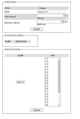
Note that if you did not follow the above procedure and only check the Enable box and click Update button. An error message will be displayed as shown in Figure 2.185.
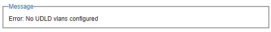
UDLD Port-info
This submenu provides information about ports that are monitor for unidirectional problem called UDLD ports as shown in Figure 2.192. The user can check the information about VLAN ID, Port, Link, State, and Neighbor Information in each entry. The Neighbor Information also consists of Device ID, Device Name, Port ID, and Hello interval. An example of UDLD entry is depicted in Figure 2.186.
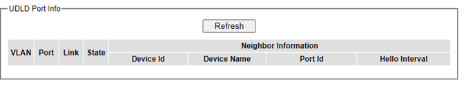
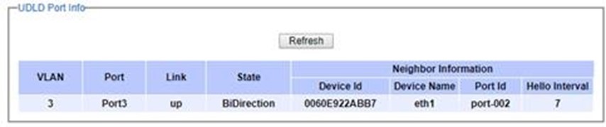
UDLD Reset
This submenu allows the user to reset all UDLD ports that were shut down by UDLD protocol as shown in Figure 2.188. The use can click on the Reset button to reset the UDLD port.
Client IP Setting
The EHG7XXX industrial managed switch has two different approaches for setting up the IP addresses for the devices connected to its ports. The following are the submenus under the Client IP Setting section:
DHCP Relay Agent,
DHCP Mapping IP.
Figure 2.189 shows the dropdown menus under the Client IP Setting section.
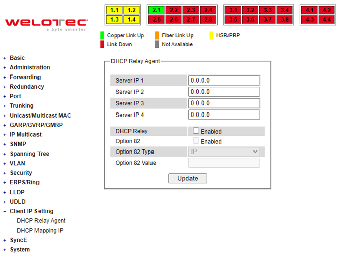
DHCP Relay Agent
A DHCP relay agent is a small program that relays DHCP/BOOTP messages between clients and servers on different subnets. DHCP/BOOTP relay agents are parts of the DHCP and BOOTP standards and function according to the Request for Comments (RFCs).
A relay agent relays DHCP/BOOTP messages that are broadcast on one of its connected physical interfaces, such as a network adapter, to other remote subnets to which it is connected by other physical interfaces. Figure 2.196 shows the DHCP Relay Agent setting webpage. The users can enter up to four DHCP/BOOTP server IP addresses in the fields: Server IP 1, Server IP 2, Server IP 3, and Server IP 4. Then the users can enable the DHCP Relay by checking the Enabled box behind the DHCP Relay option.
The users can also have a choice to enable DHCP’s Option 82 which is the DHCP Relay Agent Information Option. When this Option 82 is enabled, the switch will insert information about the client’s network location into the packet header of DHCP request coming from the client on an untrusted interface. Then, the switch will send the modified request to the DHCP server. The DHCP server will inspect the option 82 information in the packet header and use it to generate the IP address or other parameters for the client. When the DHCP server returns the response to the switch, the switch will remove the option 82 information from the response packet and forward it to the client. The Option 82 Type field in Figure 2.190 can be chosen from IP, MAC, Client-ID, or Other in the dropdown list. When Other type is selected, the Option 82 Value field will become active for entering the desired value by the users. After finishing the DHCP Relay Agent setup, please click on the Update button to allow the change to take effect.
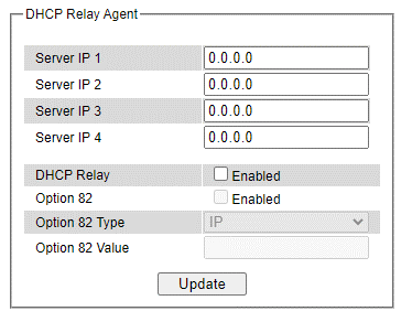
DHCP Mapping IP
The user can reserve or map IP addresses to the device connected on the selected ports in this submenu. Figure 2.191 shows the DHCP Mapping IP webpage where the desired IP address can be entered into the field for each Port. After finishing the DHCP IP mapping to the port(s), please click on the Update button to allow the change to take effect.
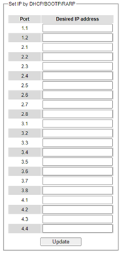
System
This last section on the Web UI interface of the RSAGS managed switch provides miscellaneous tools for network administrator to check the internal status of the switch via system log, warning, and alarm notification. It also allows the administration to perform device maintenance operations such as backing up and restoring device’s configuration, updating the firmware, reversing the device to factory default setting, or reboot the system/device. Figure 2.192 shows all the dropdown menus under the System section.
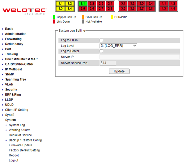
It is important for network administrators to know what’s happening in their networks and know where the events are happening. However, it is difficult to promptly locate network devices that are at the endpoints of systems. Thus, Ethernet switches connected to these devices play an important role of providing first-moment alarm messages to network administrators, so that network administrators can be informed instantaneously when accidents happen. Email alerts and relays outputs under the System section is used to provide fast and reliable warning alerts for administrators.
System Log
The submenus under the System Log are: Setting and Log.
System Log Settings
Figure 2.193 shows System Log related settings configuration. The actual recorded log event will be shown in Event Log on the next subsection. Here the users can enable how the log will be saved and/or delivered to other system. The log can be saved to flash memory inside the managed switch and/or it can be sent to a remote log server. The users need to select the log level and provide the IP address of a remote log server and the service log service port. Please click on the Update button after finishing the setup. Table 2.67 describes the details of parameters setting for the system log.
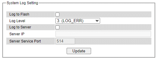
Table 2.67 Descriptions of System Log Settings:
Label |
Description |
Factory Default |
|---|---|---|
EnableLog Event to Flash |
Checked: Saving log event into flash memory. The flash memory can keep the log event files even if the switch is rebooted. Unchecked: Saving log event into RAM memory. The RAM memory cannot keep the log event files after each reboot. |
Uncheck |
Log Level |
Set the log level to determine what events to be displayed on the next webpage (Log). The level selection is inclusive. For example, if 3 :(Log_ERR) is selected, all 0, 1, 2 and 3 log levels will be implied. Range from Log 0 to Log 7. |
3: (LOG_E RR) |
Enable System Log Server |
Checked: Enable Syslog Server. Uncheck: Disable Syslog Server. If enabled, all recorded log events will be sent to the remote System Log server. |
Uncheck |
System Log Server IP |
Set the IP address of Syslog server |
0.0.0.0 |
System Log Server Service Port |
Set the service port number of System Log server. Range from Port 1 to Port 65535. |
514 |
System Log - Log
Figure 2.194 shows an example of all the event’s logs. Note that they are sorted by date and time. Table 2.68 provides explanation of each column and the button’s functions on the System Log webpage.
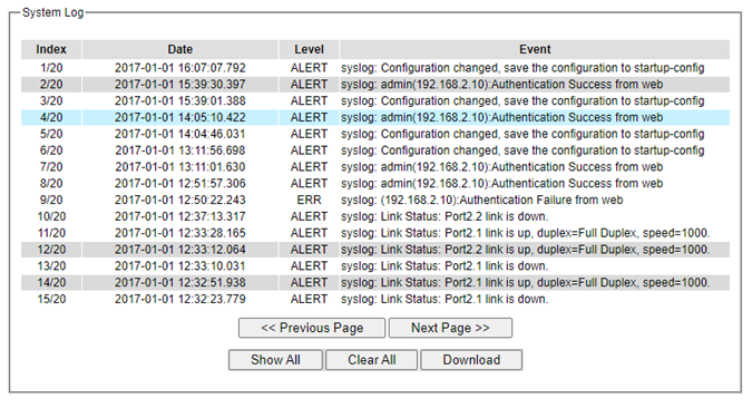
Table 2.68 Descriptions of Event Log:
Label |
Description |
|---|---|
Index |
Indicate the index of a particular log event |
Date |
Indicate the system date of theoccurred event |
Time |
Indicate the time stamp that this event occurred |
Up Time |
Indicate how long the system (managed switch) has been up since this event occurred. |
Level |
Indicate the level of this event. |
Event |
Detailed description of this event. |
Previous Page |
Display events on the previous page. |
Next Page |
Display events on the next page |
Show All |
Click to display all events. |
Clear All |
Click to clear all events |
Download |
Download or save the event log to the local computer |
Warning/Alarm
The warning/alarm section consists of three subsections: Setting, SMTP Setting, and Log.
Warning/Alarm Settings
There are three different types of Warning or Alarm: Link Status Alarms, Power Status Alarms, and System Log Alarms as shown in Figure 2.195. The Link Status Alarms are related to the activities of port(s). Power Status Alarms keep track of power status of the switch based on the available input connectors. System Log Alarms are related to the overall functionalities of the switch. This webpage allows the users to configure how each type of the alarm events will be sent or notify the users. For link status and power status alarms, there are three possible notification methods via Relay, E-mail, and Alarm LED. For System Log alarms, there are only two possible notification methods via Relay and E-mail. After finish configuring the alarms, please click the Update button. Note that there is an Assert Relay button which can be used to test an external Relay connected to the managed switch.
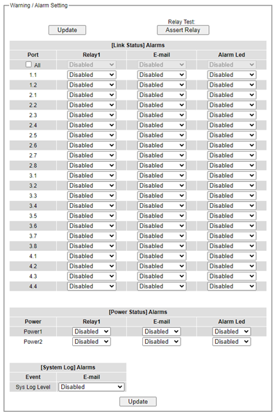
In Link Status Alarms, users have three conditions whether to send notifications via Relay, E-mail, or Alarm LED in case if Link is UP, Link is Down, or Link is UP/DOWN. Table 2.69 summarizes the link status alarm event selection. Note the users can enable the alarm events for all ports simultaneously by checking the box in front of the All entries.
Table 2.69 Descriptions of Link Status Alarm Event Selection:
Label |
Description |
Factory Default |
|---|---|---|
Port |
Indicates eachport number. |
- |
Port state event |
Disabled: Disables alarm function, i.e. no alarm message will be sent. |
Disabled |
In power status alarms, the users have two conditions to send notification (via Relay, E-mail, and Alarm LED) which are Power On, or Power Off. Table 2.70 summarizes the Power Status Alarm event selection.
Table 2.70 Descriptions of Power Status Alarm Event Selection:
Label |
Description |
Factory Default |
|---|---|---|
Power |
Indicate specific power supply |
Disabled |
Power status event |
Disable: Disables alarm function. |
Disabled |
In System Log Alarms, the users have can only send notification via Relay and E-mail. Table 2.71 describes the System Log Level which can be selected for the System Log Alarm event notification.
Table 2.71 Descriptions of System Log Alarm Event Selection:
Label |
Description |
Factory Default |
|---|---|---|
System log event |
Disable: Disable power status detection. |
Disabled |
*NOTE: - Log levels are inclusive. In other words, when log level is set to 0, an alarm is triggered whenever 0, 1, 2… 6, and/or 7 happens. When log level is set to 5, an alarm is triggered whenever 5, 6, and/or 7 happens.
0: Emergency: system is unstable 1: Alert: action must be taken immediately 2: Critical: critical conditions 3: Error: error conditions 4: Warning: warning condition 5: Notice: normal but significant condition 6: Informational: informational messages 7: Debug: debug-level messages
SMTP Settings
Simple Mail Transfer Protocol (SMTP) is an internet standard for email transmission across IP networks. In case any warning events occur as configured in Section 2.20.2.1, the system can send an alarm message to users by e-mail. Here, the users will be allowed to modify E-mail-related settings for sending the system alarms (Link Status, Power Status, and System Log), as shown in Figure 2.196.
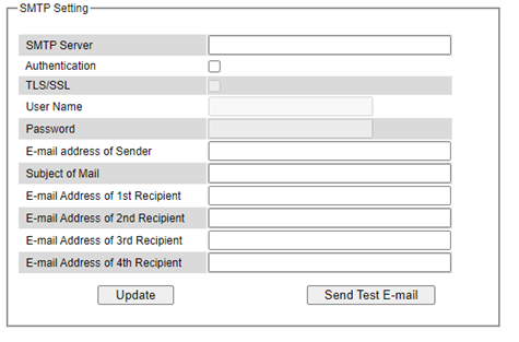
An example of SMTP Setting is shown in Figure 2.197. After entering all the necessary fields, please click on the Update button to allow the setting to take effect. Note that the users can try to send a Test E-mail according to the SMTP setting on this webpage by clicking on the Send Test E-mail button. The description of each SMTP Setting parameter is summarized in Table 2.72.
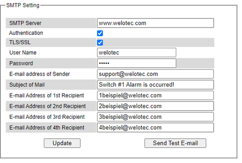
Table 2.72 Descriptions of SMPT Setting:
Label |
Description |
Factory Default |
|---|---|---|
SMTP Server |
Configure the IP address of an out-going e-mail server |
NULL |
Authentication |
Enable or disable authentication login by checking on the box. If enabled, SMTP server will require authentication to login. Thus, the users will also need to setup Username and Passwordto connect to the SMTP server |
Disable (Unchecked) |
TLS/SSL |
Enable or disable Transport Layer Security (TLS) or Secure Sockets Layer (SSL) which is an encryption mechanism for communication with the SMTP Server |
Disable (Unchecked) |
Username |
Set the username (or account name) to login.Max. 31 char. |
NULL |
Password |
Set the account password for login.Max. 15 characters. |
NULL |
E-mail Address of Sender |
Configure the sender e-mail address |
NULL |
Mail Subject |
Type the subject of this warning message.Max. 31 characters. |
NULL |
E-mail Address of 1st Recipient |
Set the first receiver’s E-mail address. |
NULL |
E-mail Address of 2nd Recipient |
Set the second receiver’s E-mail address. |
NULL |
E-mail Address of 3rd Recipient |
Set the third receiver’s E-mail address. |
NULL |
E-mail Address of 4th Recipient |
Set the fourth receiver’s E-mail address. |
NULL |
Update |
Update these modificationson the managed switch |
- |
Send Test E-mail |
Send a test email to recipient(s) above to check accuracy. |
- |
Log
Managed switches warn its users in case any event occurs. A table called Warning/Alarm Log in this section displays the warning events as shown in Figure 2.198 Warning/Alarm Log Webpage. At the top of the table, the users can click on the Reset Relay button to turn off the Relay or click on the Clear Log to remove all entries in the Warning/Alarm Log table. To obtain the latest event on the able, the users must click on the Refresh button.
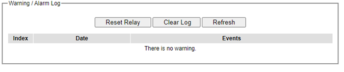
An example of Warning/Alarm Log table is shown in Figure 2.199. Note that the display format and buttons is slightly different from the current RSAGS format above. A short list of alarm messages is shown on the top portion of the web browser interface.

Table 2.73 Descriptions fo Warning/Alarm Log
Label |
Description |
Factory Default |
|---|---|---|
Reset Relay |
Sets Hardware Relay Alarm to off. |
Relay is off |
Clear Log |
Clears all warning events that are displayed. |
- |
Refresh |
Obtain the latest Warning/Alarm events |
- |
Index |
Display the index of the Warning/Alarm events as an entry number over a total number of events |
- |
Date |
The date that the alarm/event occurred. |
- |
Time |
The time that the alarm/event occurred. |
- |
Startup Time |
The duration of time since the start up time of the switch until the alarm/event occurred. |
- |
Events |
Description of the alarm events |
- |
Denial of Service
Denial of Service (DoS) is a malicious attempt to make a machine or network resource unavailable to its intended users, such as to temporarily or indefinitely interrupt or suspend services of a host connected to the Internet. EHG7XXX industrial managed switch is designed so that uses can filter out various types of attack as shown in Denial of Services setting webpage (Figure 2.200). The followings are some vulnerable attacks that can be prevented by the EHG7XXX switch function.
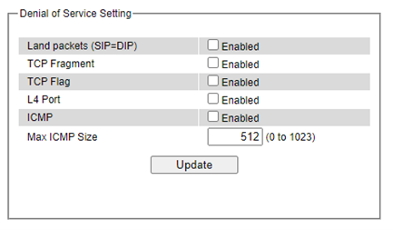
First is the Local Area Network (LAND) DoS attack. LAND is a layer 4 DoS attack in which the attacker sets the source and destination information of a TCP segment to be the same. Specifically, TCP SYN packet is created such that the source IP and port are set to be the same as the destination address and port, which in turn is set to point to an open port on a Victim’s machine. A vulnerable machine would receive such a message and reply to the destination address effectively sending the packet for reprocessing in an infinite loop. A vulnerable machine will crash and freeze due to the packet being repeatedly processed by the TCP stack. To enable/disable the protection against the Local Area Network (LAND) DoS attack, click Enabled box on LAND packet (SID=DID) function.
Second vulnerability attack is TCP fragmentation attacks also known as tear drop attack, which is targeting TCP/IP reassembly mechanism, preventing them from putting together fragmented data packets. As a result, the data packets overlap and quickly overwhelm the victim’s servers, causing them to fail. To enable/disable the protection against the TCP fragment DoS attack, click Enabled box on TCP Fragment function. However, to set the mitigation method, some certain inputs are needed to set rules of filtering. For example, whether the first fragment is allowed or not and the minimum TCP header size that is allowed. In some datalink protocols such as Ethernet, only the first fragment contains the full upper layer header, meaning that other fragments look like beheaded datagrams. No additional overhead imposed over network because all fragments contain their own IP header. Only the first fragment contains the ICMP header, and all remaining fragments are generated without the ICMP header.
The third vulnerability is called TCP flag DoS attack. The attack sends out TCP packets with flag indicating that they are ACK packets. This attack is like SYN flood except SYN flood also open a connection with the server. Although the devices are mostly tuned for more common attack as SYN flood. TCP flag DOS attack will force the server to keep dropping the packets, causing resource exhaustion. To enable/disable the protection against the TCP Flag DoS attack or called ACK flood, click Enabled box on TCP Flag function.
The fourth vulnerability is called L4 port DoS attack. There are various types of L4 port DoS attack. In UDP attack, many UDP packets are sent to victim until it is overloaded. UDP-Lag attacks in bursts as to not hit the target offline completely. SUDP attack is the same as UDP but spoofs the request to make it harder to mitigate. SYN/SSYN/ESSYM attacks are abuse the handshake of the TCP protocol until the victim is overloaded. DNS/NTP/CHARGEN/SNMP attacks are an amplified UDP attack that abuses vulnerable server by sending a spoofed request with the targets IP as the sender. The servers then send the target the information overloading the system. To enable/disable the protection against all these L4 Port DoS attacks, click Enabled box on L4 Port function.
Last vulnerability is so called ICMP fragmentation attack. The attack involves the transmission of fraudulent ICMP packets that are larger than the network’s MTU. In this switch, administrators can filter these packets out by enabling ICMP function and set Maximum ICMP size range from 512 to 1023 bytes. As these ICMP packets are fake, and are unable to be reassembled, the target server’s resources are quickly consumed, resulting in server unavailability. To enable/disable the protection against the ICMP DoS attack, click Enabled box on ICMP function. Table 2.74 provides descriptions of the Denial of Services Setting.
Table 2.74 Descriptions of Denial of Services Setting:
Label |
Description |
Factory Default |
|---|---|---|
LAND packets |
Enabled: Enabled prevention over the attack using TCP SYN packet that has the same source and destination’s IP and port. |
Disabled |
TCP Fragment |
Enabled: Enabled prevention over the TCP fragmentation attack which is targeting TCP/IP reassembly mechanism |
Disabled |
TCP Flag |
Enabled: Enabled prevention over the TCP flag DOS attack which force the server to keep dropping the packets, causing resource exhaustion. |
Disabled |
L4 Port |
Enabled: Enabled prevention over various types of L4 port DoS attacks that are intended to overload the server. |
Disabled |
ICMP |
Enabled: Allow filtering ICMP that has packet size higher than the maximum ICMP size defined in the next field |
Disabled |
Max ICMP Size |
512 to 1023 bytes |
512 |
Backup/Restore Config.
In Backup/Restore Config function, the current configuration of the EHG7XXX industrial managed switch can be downloaded to alocal computer and saved it as a backup. Additionally, the users can restore a previously backup configuration from a local computer to the EHG7XXX industrial managed switch. It will replace the current configuration. These backups and restore functions can be done through two different protocols: HTTP or TFTP. Figure 2.201 depicts the Backup/Restore Configuration dropdown menu.
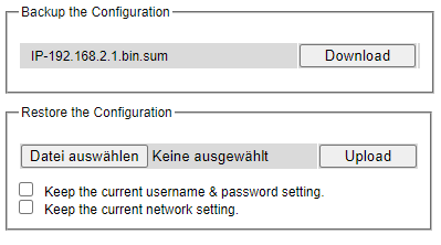
Backup/Restore Config. via HTTP
Figure 2.202 shows the webpage for Backup/Restore the configuration via HTTP. It is divided into two parts: Backup the Configuration and Restore the Configuration. When clicking on the Download button on the upper part of the page (Backup the Configuration), the users will be prompted to Opening the file name IP-192.168.2.1/24 bin by an application or to Save File to a destination. Choosing to Save File will back up the switch’s current configuration to your local drive on the local computer.
To restore a configuration file to the switch, please move down to the Restore the Configuration part, then click the Browse… button to choose a configuration file from the local drive. Before clicking the Upload button, the users can check any of the options below the upload file which are to Keep the current username & password setting and to Key the current network setting. This will help prevent the users from the necessity to login using a previously stored username, password or network configuration after settings are restored.
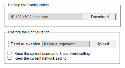
Backup/Restore Config. via TFTP
Trivial File Transfer Protocol (TFTP) is designed to be small and easy to implement. The users are allowed to upload configuration settings to a TFTP server as a backup copy, and download these settings from a TFTP server, when necessary, to restore or replace the configuration of the RSAGS industrial managed switch. Figure 2.203 shows the TFTP webpage which is divided into three parts: Download the Configuration from TFTP, Upload the Configuration to TFTP, and DHCP Option 66/67 Setting. Table 2.75 summarizes the descriptions of TFTP Setting.
To download a configuration file from a TFTP server, the user needs to specify the IP address of the TFTP server and the Remote File Name. Then, click the Download button.
To upload a configuration file from a TFTP server, the users need to specify the IP address of the TFTP server and the Desired File Name. Then, click the Upload button.
The last part of the TFTP page is the DHCP Option 66/67 Setting. This feature enables the managed switch to learn of the TFTP Server Name, which is a data in DHCP IPv4 packet Option 66 (RFC2132), and Filename, which is a data in DHCP IPv4 packet Option 67 (RFC2132). Checking the Enabled box and then click on the Update button to set this feature.
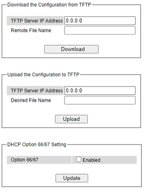
Table 2.75 Descriptions of TFTP Settings:
Label |
Description |
Factory Default |
|---|---|---|
TFTP Server IP Address |
Sets the IP address of the remote TFTP server domain name. |
NULL |
Remote File Name |
Type in name of the file to be downloaded. |
NULL |
Download |
Click to start download remote configuration into the Switch. |
- |
Desired File Name |
Type in name of the file to be uploaded. |
NULL |
Upload |
Click to start upload Switch configuration to the remote TFTP server. |
- |
Option 66/67 |
Enable this option to allow the managed switch to learn of TFTP Server Name and the filename to be used from a DHCP packet |
Disable |
Update |
Update the setting of DHCP Option 66/67 setting |
- |
Backup/Restore Config. via SCP
The users are allowed to upload configuration settings to a Secure copy (SCP) server as a backup copy, and download these settings from a SCP server, when necessary, to restore or replace the configuration of the RSAGS industrial managed switch. Figure 2.204 shows the SCP webpage which is divided into three parts: SCP Server, Username, Password and Remote File Path. Table 2.76 summarizes the descriptions of SCP Setting.
To download a configuration file from a SCP server, the user needs to specify the IP address of the SCP server, SCP Server Username, Password, and the Remote File Name. Then, click the Download button.
To upload a configuration file from a SCP server, the user needs to specify the IP address of the SCP server, SCP Server Username, Password, and the Remote File Name. Then, click the Upload button.
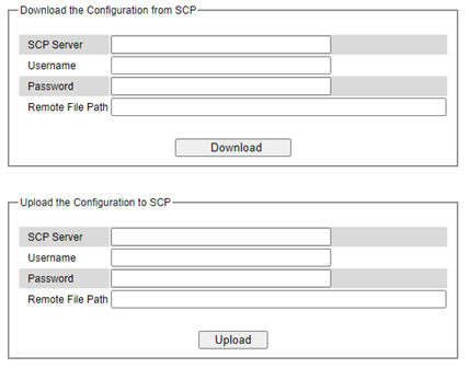
Table 2.76 Descriptions of SCP Backup/Restore Config.:
Label |
Description |
|---|---|
SCP Server |
Secure copy (SCP) server IP address |
Username |
Username for the file server |
Password |
Password for the file server |
Remote File Path |
The path of firmware file stored on the file server |
Backup/Restore Config. via SFTP
The users are allowed to upload configuration settings to a SSH File Transfer Protocol (SFTP) server as a backup copy, and download these settings from a SFTP server, when necessary, to restore or replace the configuration of the RSAGS industrial managed switch. Figure 2.205 shows the SFTP webpage which is divided into three parts: SFTP Server, Username, Password and Remote File Path. Table 2.77 summarizes the descriptions of SFTP Setting.
To download a configuration file from a SFTP server, the user needs to specify the IP address of the SFTP server, SFTP Server Username, Password, and the Remote File Name. Then, click the Download button.
To upload a configuration file from a SFTP server, the user needs to specify the IP address of the SFTP server, SFTP Server Username, Password, and the Remote File Name. Then, click the Upload button.
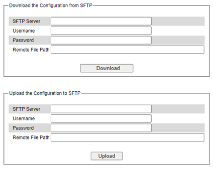
Table 2.77 Description of SFTP Backup/Restore Config.:
Label |
Description |
|---|---|
SFTP Server |
SSH File Transfer Protocol (SFTP) server IP address |
Username |
Username for the file server |
Password |
Password for the file server |
Remote File Path |
The path of firmware file stored on the file server |
Firmware Update
The users can update the device firmware via web interface as shown in Figure 2.206 To update the firmware, the users can download a new firmware from Welotec’s website and save it in a local computer. Then, the users can click Browse… button and choose the firmware file that is already downloaded. The switch’s firmware typically has a “.dld” extension. After that, the users can click Update button and wait for the update process to be done.
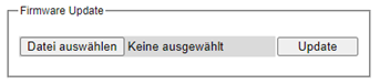
And the managed switch also supports that user can through SCP and SFTP secure file transfer protocols to remote get firmware for upgrade as shown in Figure 2.207.
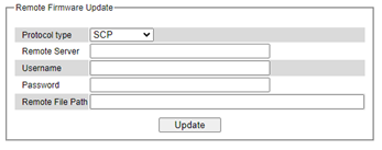
Table 2.78 Descriptions of Remote Firmware Update:
Label |
Description |
|---|---|
Protocol Type |
Choose server type to copy file, support options: SFTP/ SCP |
Remote Server |
Remote Server IP address |
Username |
Username for the file server |
Password |
Password for the file server |
Remote File Path |
The path of firmware file stored on the file server |
Note: please make sure that the switch is plug-in all the time during the firmware update.
Factory Default Setting
When the managed switch is not working properly, the users can reset it back to the original factory default settings by clicking on the Reset button as shown in Figure 2.208.
Reboot
An easy reboot function is provided in this webpage requiring only one single click on the Reboot button as shown in Figure 2.209.
Logout
A logout function is provided in this webpage requiring only one single click on the Logout button as shown in Figure 2.210.